


Hardware components | ||||||
| × | 1 | ||||
| × | 1 | ||||
| × | 1 | ||||
| × | 1 | ||||
| × | 1 | ||||
| × | 1 | ||||
Software apps and online services | ||||||
 |
| |||||
Hand tools and fabrication machines | ||||||
 |
| |||||
 |
| |||||
This is my build of a project called Puzzle using 7 keys and 7 LEDs by fellow Hackster Klausj. It is a simple puzzle where the objective is to light up 7 lights. What makes it into a puzzle is changing the state of one of the lights alters the state of the lights belonging to its immediate neighbors.
The build is centered around a TM1638 module. These come in various configurations.
This project is built for the version on the right (JY-LKM1638). It includes 8 7-segment displays, 8 red/green LEDs and 8 switches all controlled by a TM1638 driver chip. This chip communicates to the microprocessor over three lines.
Back in June 2018 rodmod made a nice case to hold this module. I have used his design as a basis for the 3D printed case for this project. The 3D printing of the case is straight forward. I used a 0.2mm layer height, 30% infill and no supports.
Preparing the JY-LKM1638 moduleBefore you can add the JY-LKM1638 to the case, it needs some modification first.
Remove IDC connectors. As the board cost far outweighs the cost of a couple of IDC headers, I suggest you remove the IDC headers by heating each pin's solder and pulling out the pin one-by-one with pliers. Use a solder sucker to clean up the holes. Add a 5x2 right-angle pin-header to the back-side of the board as shown above.
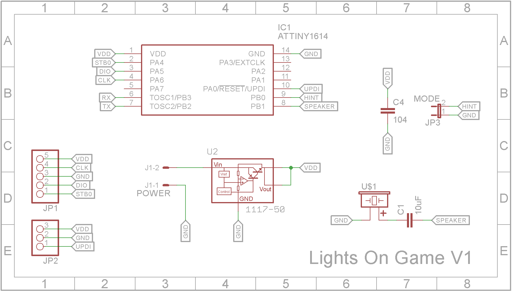
Circuit designThe Arduino Uno has been replaced with a ATtiny1614 microprocessor. A 5V regulator is included so the unit can be powered by a standard 7V to 12V DC power supply. I also added a small piezoelectric buzzer to generate some sounds.
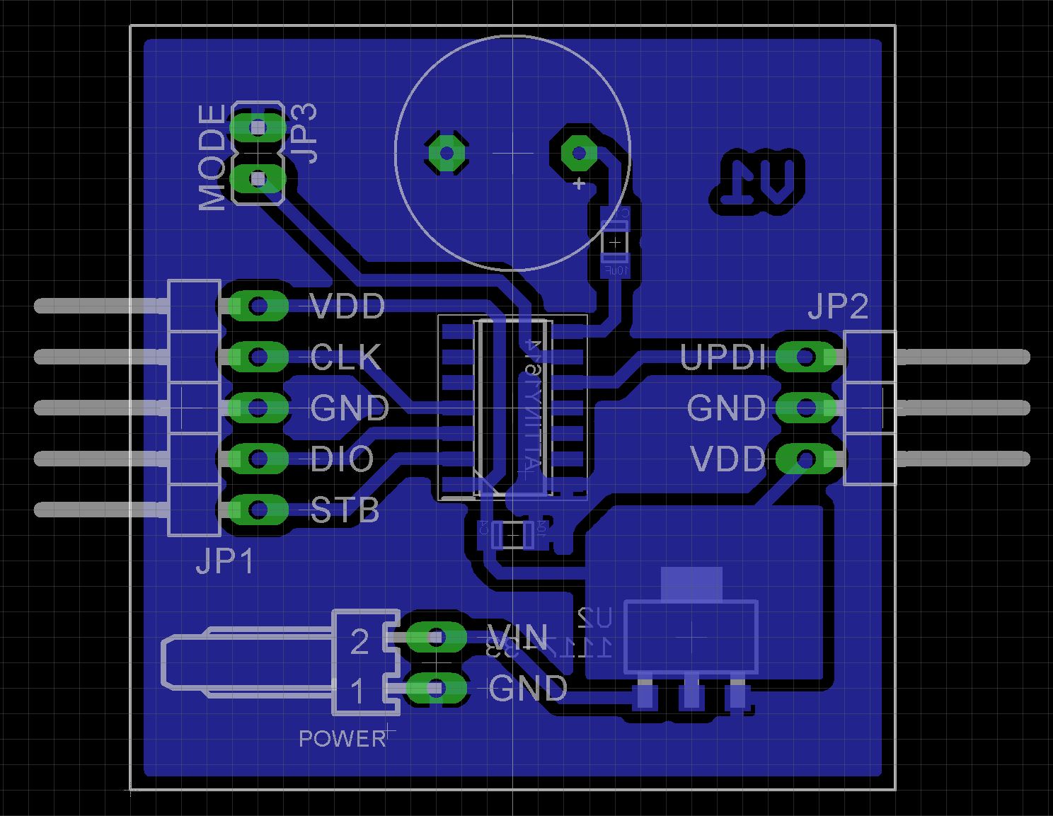
As the ATtiny1614 microprocessor only comes as a Surface Mount Device (SMD), I decided to use SMD packages for most of the components in the build.
The Eagle files have been included should you wish to have the board commercially made or you can do as I did and make it yourself. I used the Toner method.
Assembly - Step 1Start by adding the SMD components. I find it easier to use solder paste rather than use solder from a reel when soldering SMD components. I used my SMD Hot Plate to reflow the solder paste.
Next add right-angle pin headers for the display, hint jumper and UPDI programmer.
Add a 2 pin right angle KF2510 male connector for the power connection.
Add the passive piezoelectric buzzer.
Use hot glue to hold the PCB in its holder.
Add the DC panel socket to the case and wire up to the PCB.
Screw in the TM1638 board using 4 x 4mm M3 screws.
Wire the TM1638 board to the main PCB.
The ATtiny1614 is part of the new breed of ATtiny microprocessors. Unlike the earlier series such as the ATtiny85, the new breed use the RESET pin to program the CPU. To program it you need a UPDI programmer. I made one using a Arduino Nano. You can find complete build instructions at Create Your Own UPDI Programmer. It also contains the instructions for adding the megaTinyCore boards to your IDE.
Connect the ground and UPDI wires to the UPDI connector and leave the 5V wire unconnected. Power up the board using a 7V-12V supply as shown below.
Once its programmed, you can close up the case. The are 4 x 3mm holes in the base that you can use to open the case should you ever need to. Use a 3mm rod to slowly push the top out from its base.
Solving the puzzleWhen you press any of the first 7 buttons, the LED associated with that button will alter its state. Also its two neighboring LEDs will also change their state. The 7th LED and the 1st LED are neighbors. That is pressing button 1 will change the state of LED's 7, 1, 2.
On the main PCB is a link which when shorted will enable hints by pressing the 8th button. The display will tell you the next button to press. You can keep getting hints until the puzzle is solved.
Thanks Klausj for publishing your project. I finally found a use for the JY-LKM1638 module that has been lying around my workshop for what seems like a decade. It now finally has a home 🏠👏


Comments
Please log in or sign up to comment.