


Hardware components | ||||||
| × | 1 | ||||
| × | 1 | ||||
 |
| × | 5 | |||
| × | 1 | ||||
| × | 1 | ||||
| × | 1 | ||||
| × | 1 | ||||
Software apps and online services | ||||||
 |
| |||||
Hand tools and fabrication machines | ||||||
 |
| |||||
 |
| |||||
Maze Runner generates a random maze and allows the user to do a virtual walk-through of the maze to find the exit.
Maze Runner starts by generating a random maze and shows you the path to the exit. You will always start in the top-left and exit in the bottom-right. After you are shown the path to the exit, your start position is shown by a flashing dot.
When the 3D view is shown, you will be facing one of the four compass positions, that is: N, E, W, S. The top of the maze map is north.
Use the X-pad to move/look around the maze. Left and Right buttons will rotate your view without moving. The direction you are looking is shown as a point on a compass. The Up button will move you forward. Holding the button down will allow you to quickly move down corridors. Similarly the Down button will move you backwards.
The short press of the FIRE button will generate a new random maze. This project started out as a generic game console hence the name of the switch. To switch off the console, hold down the FIRE button until the screen switches off and the microprocessor is placed into sleep mode. Pressing the FIRE button while in sleep mode will wake the microprocessor up.
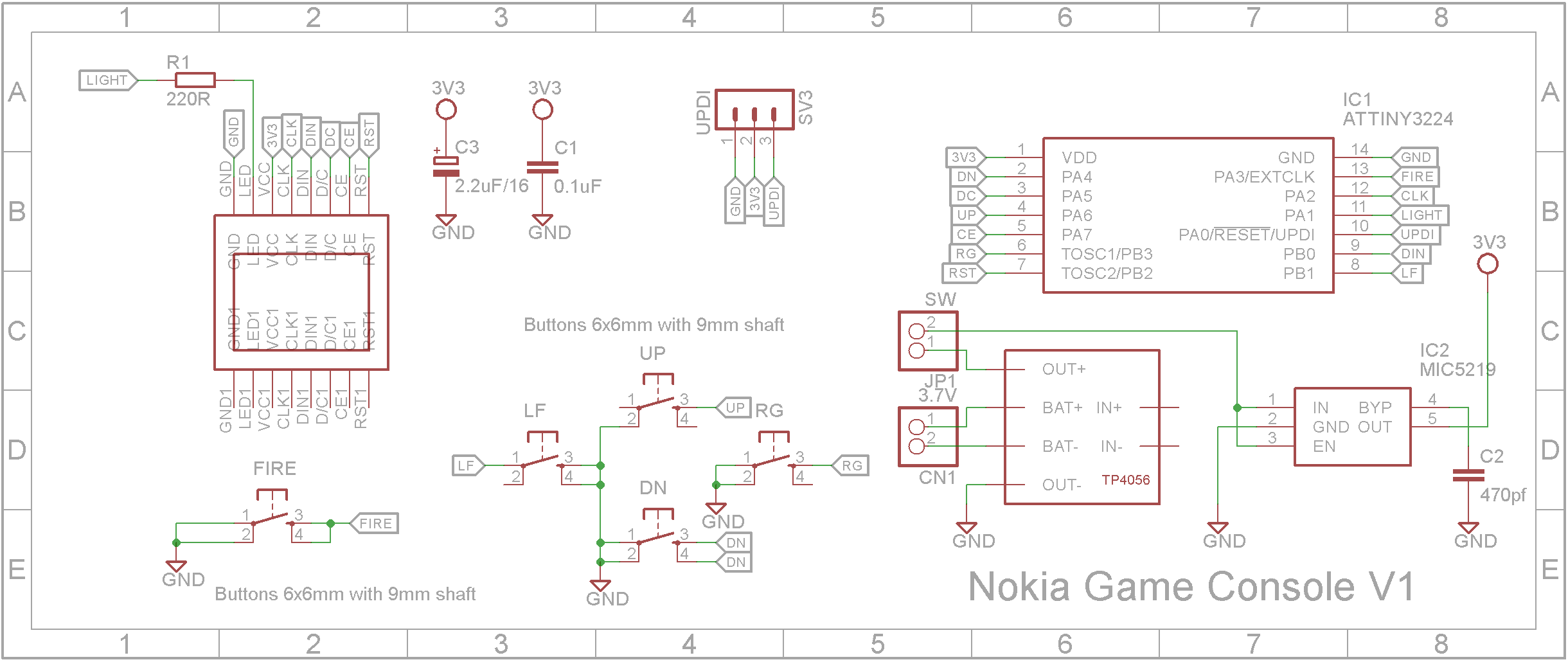
VideoDesignThe game console is designed to be generic and can be reprogrammed to play other games and puzzles.
I chose to use a ATtiny3224 Microprocessor. It runs at 20MHz, has 32K Flash memory and 3k of RAM. It comes in a 14 pin SOIC package.
The unit is powered by a Li-Ion 400mAhr battery which is charged via a TP4056 charging module. The screen and microprocessor runs at 3.3V via a low drop-out voltage regulator.
Using the STL files provided, print the bottom and the top. I used a 0.2mm layer height and no supports.
Use a 0.1mm layer height when printing the X-Pad and the supports.
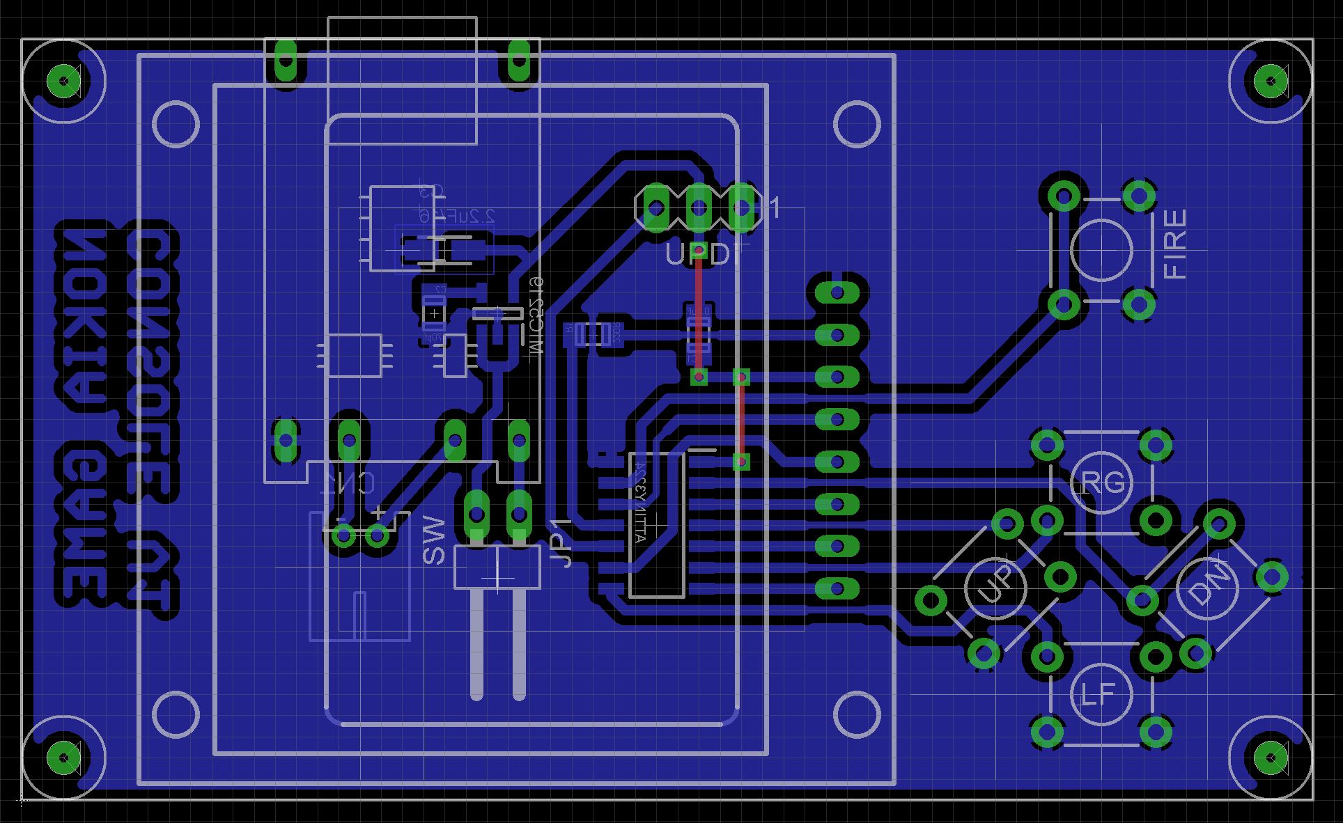
Building the electronicsAll the electronics are mounted on a PCB. With the exception of the switches and Nokia 5110 display, SMD devices have been used exclusively. The Eagle files have been included should you wish to get the board commercially made or you can make it yourself. I used the Toner method to make mine.
Start by adding the SMD components. I find it easier to use solder paste rather than use solder from a reel when soldering SMD components. I used my SMD Hot Plate to reflow the solder paste.
Next add the links if you are using a single sided PCB
Use double-sided tape to hold the TP4056 charger module to the component side of the PCB before soldering the six connections to the board using tinned copper wire.
Add the 3 pin right angle pin header for the UPDI programmer. Glue the small 3D printed support under the plastic portion of the header to lift the pins further from the PCB.
Add a 2 pin right angle pin header for the power switch. (Note, I didn't add one so I used a jumper to join the two pins).
Add 4 x 6x6mm tactile switches with a 6mm shaft for the X-pad.
Add a 6x6mm tactile switch with a 9mm shaft with button top for the FIRE button.
Glue on the display supports.
Add the battery socket to the copper-side of the PCB.
Solder on the Nokia 5110 display.
Insert the X-pad into its respective hole and screw the PCB to the top of the case using 4 x 4mm M2 screws.
Fit the battery in the bottom of the case and plug into the board.
Close the case.
Unlike the earlier ATtiny series such as the ATtiny85, the ATtiny1614 uses the RESET pin to program the CPU. To program it you need a UPDI programmer. I made one using a Arduino Nano. You can find complete build instructions at Create Your Own UPDI Programmer. It also contains the instructions for adding the megaTinyCore boards to your IDE.
Only the GND and UPDI pins should be connected. Do not connect the 5V supplyfrom the programmer. The battery will be providing the power the microprocessor.
Once the board has been installed in the IDE, select it from the Tools menu.
Select the ATtiny3224 board in your IDE
Select Board, chip, clock speed, COM port the Arduino Nano is connected and the programmer
The Programmer needs to be set to jtag2updi (megaTinyCore).
Open the sketch and upload it to the ATtiny3224.
Note: Do not plug in the unit while the UPDI programmer is connected.
ConclusionMaze Runner turned out to be a good test of memory by trying to memorize the maze map and then testing your spatial abilities to interpret that map through a virtual view of the maze in a 3D view.
Some future enhancements could be to have a countdown timer and see if the player can find the exit before the time runs out.
All in all it was a satisfying project 😃.


Comments
Please log in or sign up to comment.