A diode is designed to conduct current in one direction only.
Diodes when operating in the forward direction have a small voltage drop (around 0.2V to 0.7V). They have a large voltage drop when wired in their reverse direction. The popular 1N4001 diode has a reverse voltage of 50V or higher and the 1N4007 diode has a reverse voltage of 1000V or higher. What this means is that when their reverse breakdown voltage is exceeded, they will start to conduct current.
A Zener diode is a normal diode designed with a specific breakdown voltage.
Above is a typical use of a Zener diode. The resistor value is chosen to limit the current that flows through the diode. Using Ohms law, if the Zener diode is designed to dissipate a maximum of 1/2 Watt, the maximum current that can flow through it is 0.5 / 5.1 = 98mA. The resistor needs to drop 3.9V so the resistor value is 3.9 / 0.098 = 39.8 Ohms. This is the minimum value for the resistor. As current is used by the load, less current flows through the Zener diode.
InductorsThe tendency of an inductor is to resist changes in current by creating and destroying a magnetic field. Using an oscilloscope and a simple circuit with a switch, we can see how the energy built up in the inductor is released when the switch is opened. It is many times more than the voltage used to energise it.
This will form the basis of our boost converter later on. While in this case, this phenomenon is what we want, if the inductor was the coil in a relay for example, this huge back voltage would quite easily destroy the transistor or MOSFET that drives the relay. Using a diode in parallel with the inductor, you can see how these transient spikes in voltage are suppressed.
The boost convertorA boost circuit will boost the supply voltage. It primarily consists of an oscillator and transistor to energise and de-energise an inductor. You will note that previously when the inductor released its energy it produced huge positive and negative voltage swings. In a boost circuit, we only want the positive voltages to charge up a capacitor. Enter our diode to only allow positive voltages to reach the capacitor.
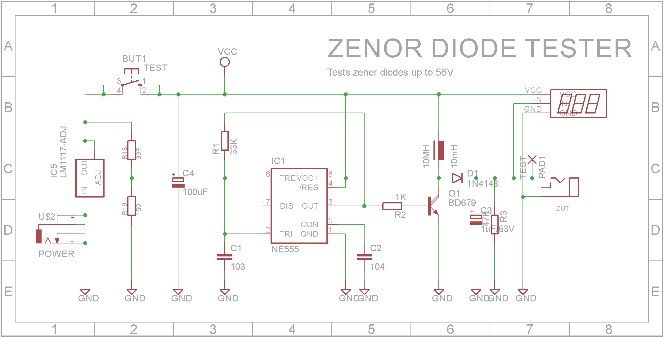
Armed with this knowledge, we can build a tester to determine the breakdown voltage of a Zener diode. (Circuit based on design by Ecco)
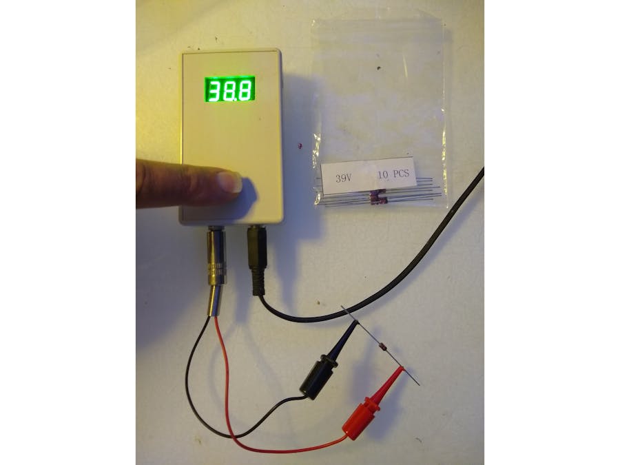
The circuit uses a 555 timer to create a square wave that is feed into a darlington transistor. The 10mH inductor charges the 1uF capacitor up to around 56V from a 6V power supply. A cheap 0-99V 3-Digit volt meter measures the output voltage. When a Zener diode under test (zut) is placed across the output, the Zener will conduct at its breakdown voltage and the volt meter will display this voltage.
Note: You may not be used to seeing the 555 wired the way it is. This method of driving the 555 timer produces a square wave with an equal mark-space ratio. (C1 charges and discharges through R1 meaning the charge and discharge period is the same).
BuildI have a number of cheap 85mmx50mmx20mm cases which I bought a while ago on eBay. They were less than a $1 each.
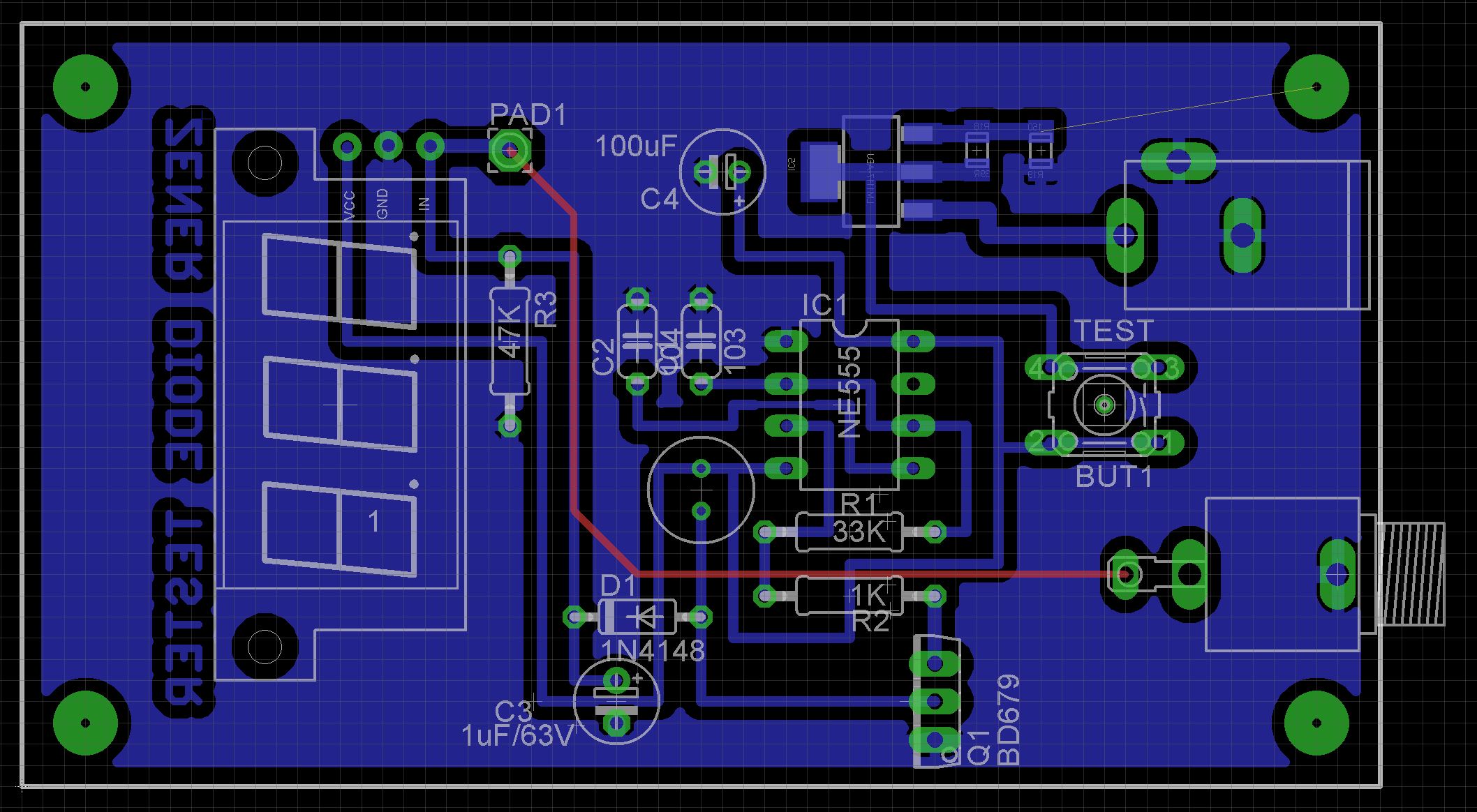
The Eagle files for the PCB have been included should you wish to get them commercially made or you can choose to make them yourself. I used the Toner method to make mine.
The PCB is designed for the following voltmeter that I obtained from eBay
- R1 33K ohm
- R2 1K ohm
- R3 47K ohm
- R18 39 ohm
- R19 150 ohm
- C1 0.01uF Monolithic Ceramic
- C2 0.1uF Monolithic Ceramic
- C3 1uF 63V Electrolytic
- C4 100uF 16V Electrolytic
- L1 10mH Inductor
- D1 1N4148 diode
- Q1 BD679 NPN Darlington transistor
- IC1 NE555 timer ic
- IC5 LM1117-ADJ regulator
- U$2 DC POWER JACK 2.1MM BARREL-TYPE PCB MOUNT
- 6mmx6mmx17mm Tactile switch
- 3.5mm mono panel socket and plug


Comments
Please log in or sign up to comment.