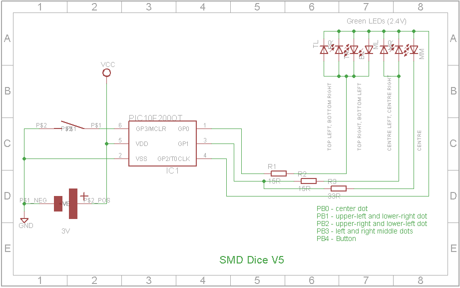
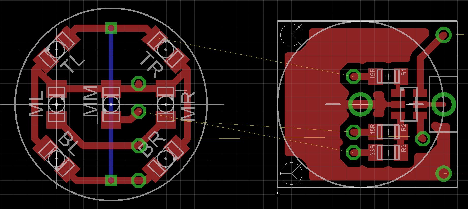
This micro dice is based on the PIC10F200 microcontroller. This 6-pin microcontroller has 375 bytes of Flash memory and 16 bytes of static RAM and 4 IO ports. Not a lot, but enough to make an electronic dice.
One IO pin is configured as a input and is connected to a vibration switch. When activated, it wakes up the microcontroller and after a short animation displays a random dice face (1 to 6) and then goes back to sleep.
At first glance at the schematic, you may be wondering how it can possibly work. The dice uses a mixture of charlieplexing and strobing different LEDs fast enough such that the human eye sees them as permanently on.
One
Showing 1 on the dice lights up the middle LED (MM) - GP2 - High, GP1 - Low
Two
Showing 2 on the dice lights up the TL and BR LEDs - GP0 - HIGH, GP2 - LOW
Three
Showing 3 on the dice lights up the TR, BL and MM LEDs - GP2 - HIGH, GP1 - LOW, GP0 - LOW
Four
Showing 4 requires switching between TR, BL LEDs and TL, BR LEDs quickly so as to appear as they are both on. GP0 - HIGH, GP2 - LOW for 50% duty cycle, GP0 - LOW, GP2 - HIGH for the other part of the duty cycle
Five
Showing 5 is the same as showing 4 but with the middle LED always ON. To keep the same level of brightness on the MM LED as the TR, BL, TL and BR LEDs, the MM LED is only on 50% of the duty cycle.
Six
Showing 6 is the same as showing 4 but with the ML and MR LEDs always ON. To keep the same level of brightness on the ML and MR LEDs as the TR, BL, TL and BR LEDs, the ML and MR LEDs are only on 50% of the duty cycle - when GP2 is LOW, GPI goes HIGH.
Programming the PIC10F200 MicrocontrollerYou need a special adaptor to program the PIC10F200. I got one off eBay and attached it to some protoboard and wired it to a pin header.
Open up the PICKit 3 software on your PC and load the attached hex file. Set the microcontroller to PIC10F200 and upload it to the chip.
3D printing the caseThe case comes in three parts. The top and bottom sections of the case and a transparent holder that sits over the LEDs and fits into the LED holes on the top part of the case. Make sure you rotate the "Dice - Led.stl" object 180 degrees about the X or Y axis in your slicer before creating the GCODE for your 3D printer.
Assembling the Micro DiceThe Eagle files have been included should you wish to get the boards commercially made or you can make them yourself. I used the toner method to make mine.
Start assembling the LED board. Take care to ensure the LEDs are soldered the correct way around. Add the link if you have single sided boards. Connect the four wires that go to the MPU board. Using a 3V supply and a 100 ohm resistor, test the LEDs against the circuit diagram to ensure the all work and you have them orientated correctly. Once this is done, super glue the LED lense part to the board.
Next assemble the microprocessor board. Start by adding the surface mount components, followed by the wires from the LED board, then add the battery holder and finally add the vibration switch.
Add the battery and put the assembly inside the case.
ConclusionIt turned out to be an interesting project taking a lot longer than I thought it would. If I build another version of this, I would replace the vibration switch with a mercury switch and use a double sided board. I would mount the LEDs on one side and the PIC10F200 and associated resistors on the other side.


Comments