

Hardware components | ||||||
| × | 1 | ||||
| × | 1 | ||||
 |
| × | 1 | |||
 |
| × | 1 | |||
| × | 1 | ||||
| × | 1 | ||||
Today microprocessors tend to dominate many of the electronic projects that are built today. They reduce component counts and are becoming even more versatile. Even the new tinyAVR® microprocessors now have programmable user circuits built in. 40 years ago when microprocessors were limited and quite expensive, many projects involved a number of discrete components and basic integrated circuits.
Going back through an archive of old electronic magazines, the following metronome circuit looked an interesting build.
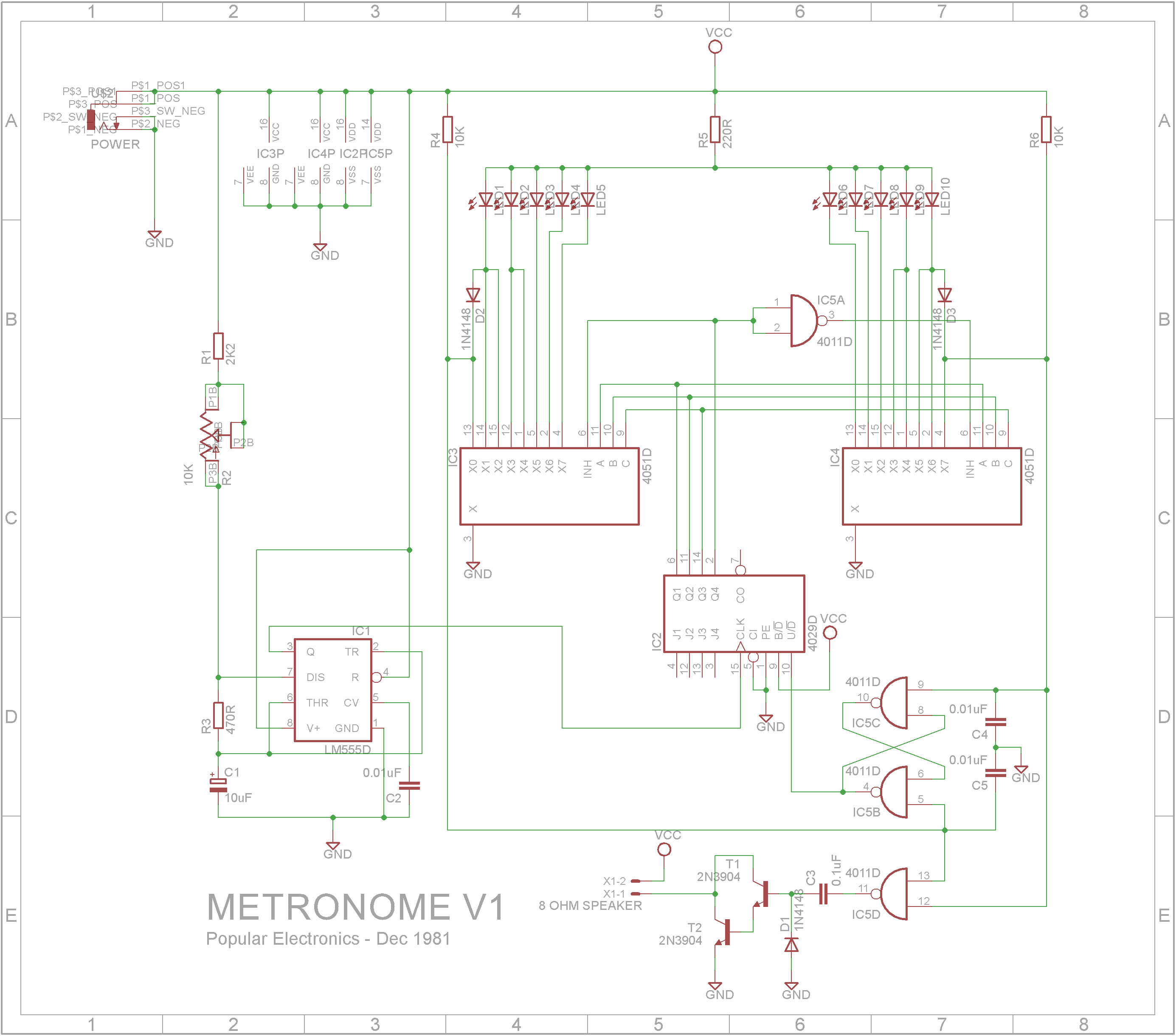
At first the circuit might seem quite complicated, but if you break it down into its logical parts, it is actually quite simple.
Let's start with the oscillator. You have probably run across a 555 astable multivibrator before. R1, R2, R3 and C1 control the frequency of a square wave that is outputted from the 555 IC on pin 3.
The clock signal is feed into a Up/Down binary counter (4029 ic). Q1 to Q4 are the outputs of the counter, Q1 being the least significant bit and Q4 being the most significant bit. Whether the counter counts up or counts down depends on whether pin 10 (U/~D) is in a high or low state. This pin is connected to what is known as a R-S flip-flop. It comprises of two 2-Input NAND gates. Under normal circumstances both the R and S inputs are held in a HIGH state.
When the S pin is pulsed LOW for a short period, the output of IC5B will go HIGH and the output of IC5C will go LOW there-by always keeping the output of IC5B at a HIGH state.
When the R pin is pulsed LOW for a short period, the output of IC5C will go HIGH and the output of IC5B will go LOW there-by always keeping the output of IC5C at a HIGH state and the output of IC5B at a LOW state.
Now comes the interesting part. The display section is made up of two 4051 8- channel multiplexers driving 10 LEDs. A multiplexer is like a 1 pole 8 way rotary switch. The A, B and C inputs determine which channel (X0 to X7) will be connected to X (pin 3). The X pin is grounded which means the LED corresponding to the selected channel will have its cathode grounded while its anode is connected to VCC via R5 (current limiting resistor).
The 4051 multiplexer as an inhibit pin (pin 6) which when HIGH disables all the outputs. You will note that this pin is connected to the most significant bit of the counter and the second 4051 multiplexer has its inhibit pin connected via an inverter made up of a NAND gate (IC5A). This means when the D line is LOW, IC3 is active and when HIGH, IC4 is active.
Now the final part of this circuit is the two Resistor/Capacitor networks (R4, C4 and R6, C5) that are connected to the first and last output of the 4051s. Looking at the X0 output on IC3, when it is output is active, X0 will be LOW and the S line will go LOW. When X0 goes inactive, R4 will charge C4 and after a short period the S line will go HIGH again. This pulse will cause the Up/Down counter to count up and the R-S flip-flop will keep the counter counting up. Similarly when the X7 output of IC4 goes LOW, the R line will get a LOW pulse and cause the Up/Down counter to count down. Again the R-S flip-flop will keep the counter counting down.
The speaker produces a small click whenever the direction of the Up/Down counter is changed. Normally R and S are HIGH meaning the output of the NAND gate is LOW switching off T1 and T2 (arranged as a darlington pair). When a pulse is sent to either the R or S pin, the NAND gate (IC5D) will go high for a short period and charge C3. After the output of the NAND gate goes LOW again, C3 will discharge through T1 thus extending the time the transistors are on. This makes a more audible click though the speaker.
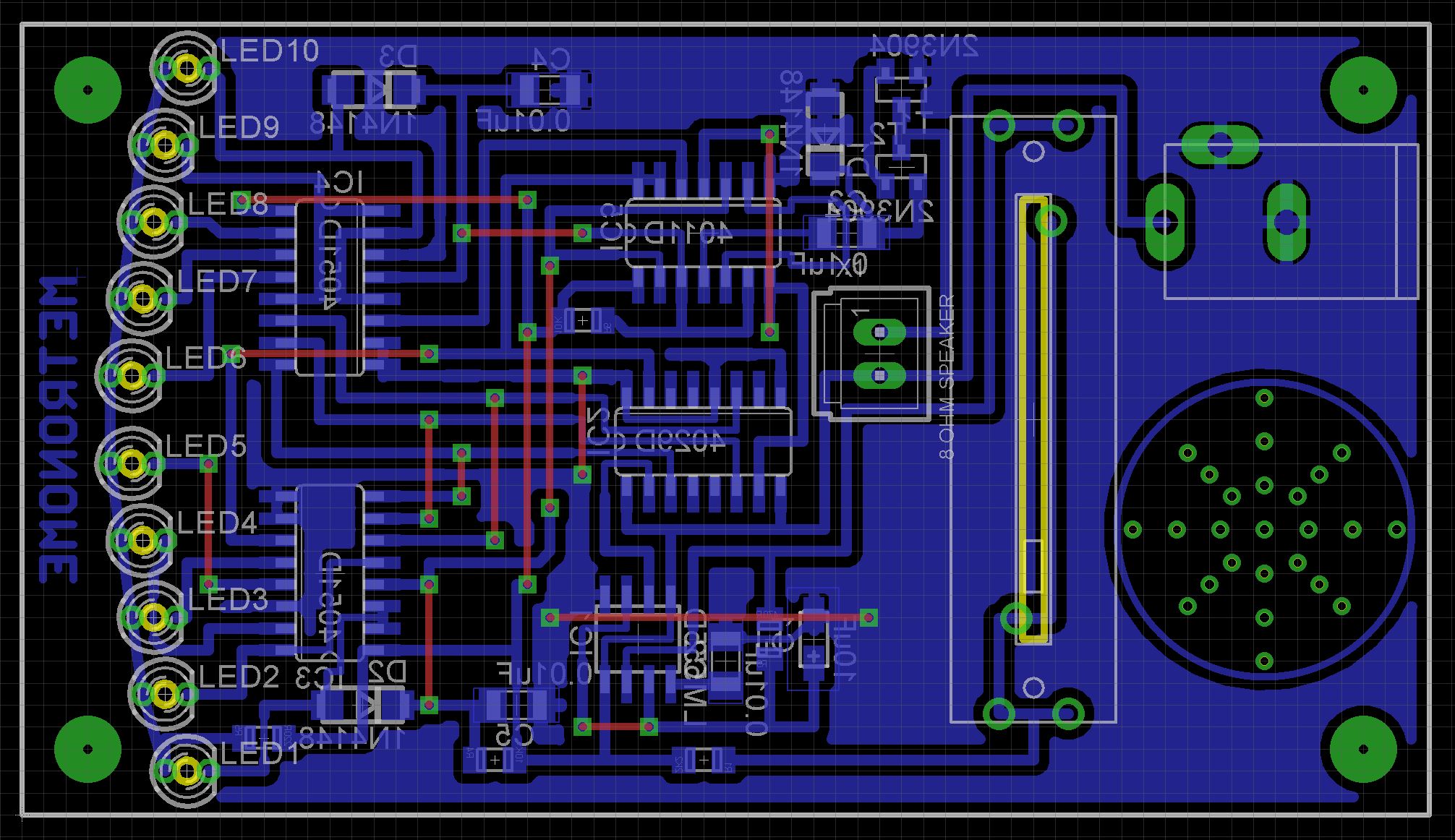
BuildI have a number of cheap 85mmx50mmx20mm cases which I bought a while ago on eBay. They were less than a $1 each. To fit this circuit into the box, a number of SMD (surface mount devices) components are used.
The Eagle files for the PCB have been included should you wish to get them commercially made or you can choose to make them yourself.
I used the Toner method to make mine and dipped them in tin solution after they were etched.
Discreet electronics without microprocessors is still fun. It's a pity in some-ways that it is a dying art but if you are interested in looking at old electronic magazines, the best source that I have found is https://worldradiohistory.com/


Comments
Please log in or sign up to comment.