This project emulates a Newton's cradle using light to demonstrate the conservation of momentum and energy. The original project was created by TecnoProfesor and can be found at RGB LED Newton's Cradle. My variant uses WS2812B NeoPixel LEDs and an ATtiny1614 microprocessor. It is enclosed in a 3D-printed case.
VideoWiring the Lamps1. 3D print five of "Newton's Swing Lamp holder.stl".
2. Wire the 5 NeoPixel LEDs with colored wire-wrap wire. The most right-hand lamp won't need the blue DOUT wire.
3. Cut 5 brass rods, 2 rods at 170mm and 3 rods at 180mm. The two shorter rods connect to the servos.
4. Insert the rod into the Lamp holder. You may need to drill out the holes with a 4mm drill first. If the fit is too loose, add a drop of super-glue to keep them in place.
5. Insert the wires and push them through the rod so that the NeoPixel LED sits flush in the holder.
6. Cut a square hole in the ping pong ball using a scalpel or similar. I found that if you put the ping ping ball on the wire-wrap spool, it won't move around so much. Ensure that the hole is big enough to take the LED and that the holder sits flat on the ping pong ball.
7. Super glue the ping pong ball in place.
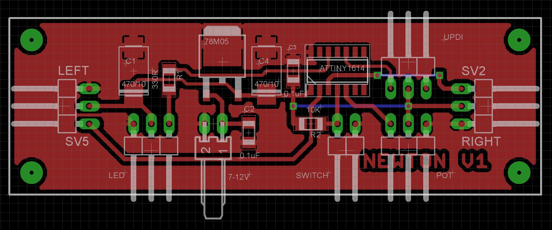
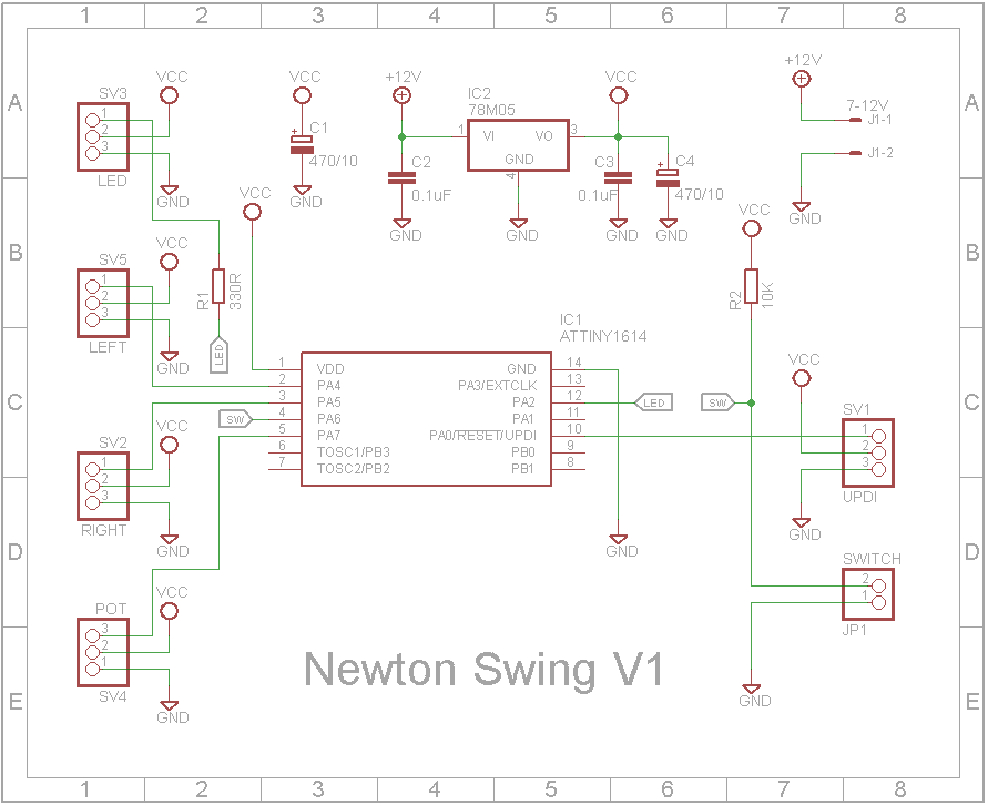
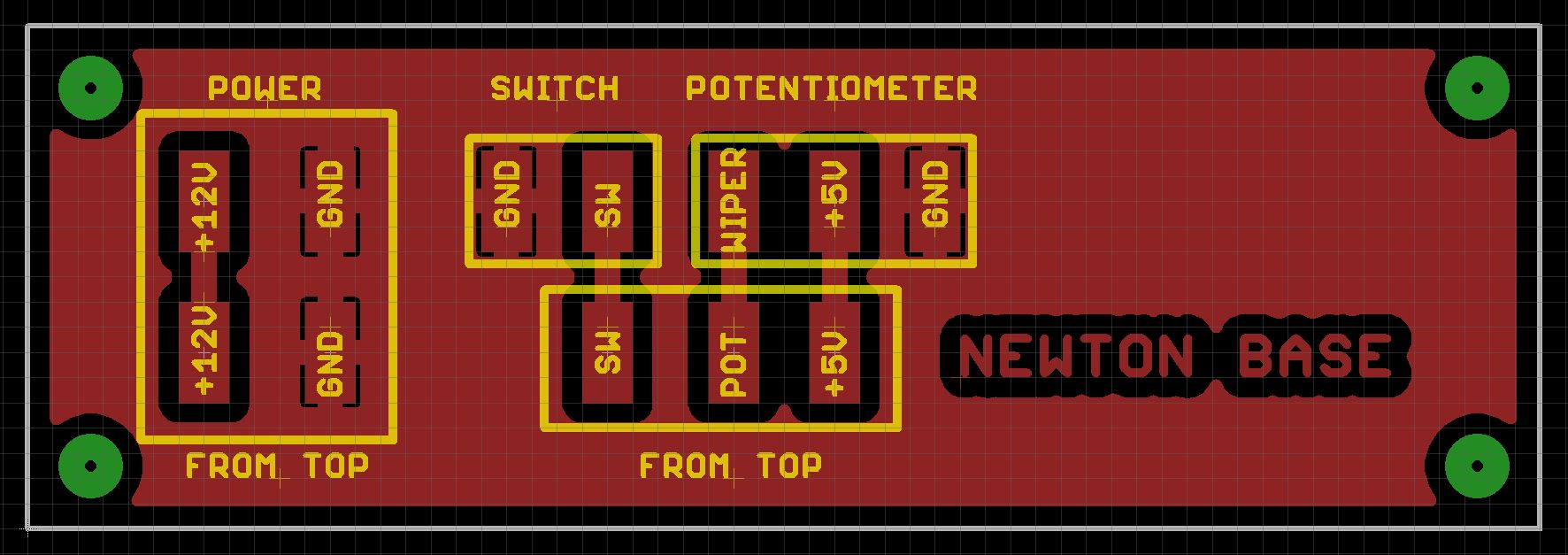
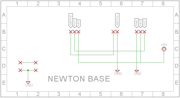
The Eagle files for the upper and lower printed circuit boards have been attached should you wish to have the boards commercially made or you can do as I did and make them yourself. I used the Toner method.
On the top board, solder the SMD components and two links. The bottom board doesn't contain any components and is only present to keep the wiring tidy and to stop the support bars from going right through.
I prefer to go the extra mile and use pin connectors on my builds mainly for ascetics. You can if you wish solder the wires directly to the board.
Add the PCB, servos and wire up the LEDs3D Print the "Newton's Swing Mount V3.stl" file. Drill out the 3 LED posts and the 2 support posts with a 4mm drill. Drill out the two PCB supports with a 2.5mm drill and create a thread using a 3mm tap. Use M3 6mm screws to fix the PCB in place.
Print two servo arms ("Newton's Swing Servo Arm.stl") and fix them temporarily to the servo splines. You may need to adjust them when the software aligns the servos to their mid-points. I painted my servo arms using brass colored paint.
You can mount the servos on to their holders.
Carefully insert the brass rods that hold the lamps into their mounts. The three 180mm rods go into the middle mounts and the two 170mm rods connect to the servos. Note: The most right hand LED has only three wires.
When wiring the LEDs, you want to start on the left and connect the DOUT wire to the DIN wire on the LED to its right. Be very careful stripping wire-wrap wire as it doesn't take much to cut through it.
Adding the supports and baseCut two 230mm brass rods to be used to support the top frame. I painted mine matt black. Insert the two rods into the top plate. Next insert them into the bottom base. You may need to use some force to get them all the way into their mounts. You will also need to support the mount you are forcing the rod into otherwise it will break. The PCBs stop the rod from going right through while still allowing the wires to connect the top and bottom sections to pass through the rod.
Finally wire up as shown below:
The ATtiny1614 is a new breed of ATtiny microprocessor. These are programmed using the RESET/UPDI pin. I have written the following tutorial on how to program these chips. See Using the New ATtiny Processors with Arduino IDE and Create Your Own UPDI Programmer.
The pin header next to the ATtiny1614 chip has the pins for VCC, UPDI and GND. Connect these to your programmer. Before you upload your sketch, disconnect the servo arms. Upload the included sketch and the servos should automatically center themselves. You can now attach the servo arms in their vertical position.
The push button circulates the operating modes between the following four states:
- OFF
- Rainbow (LEDs only - no servos)
- Swing (Standard Newton Cradle motion)
- Explode (Outside servos in unison explode into the center)
On the first iteration of the above four modes, the servos are deactivated so that you can use it purely as a desk lamp.
Once your are happy you can disconnect the programmer and add the top box section ("Newton's Swing Top.stl"). Drill out the supports with a 2.5mm drill and create a thread using a 3mm tap. Use M3 8mm screws to fix the top plate to the top cover.


_3u05Tpwasz.png?auto=compress%2Cformat&w=40&h=40&fit=fillmax&bg=fff&dpr=2)
Comments
Please log in or sign up to comment.