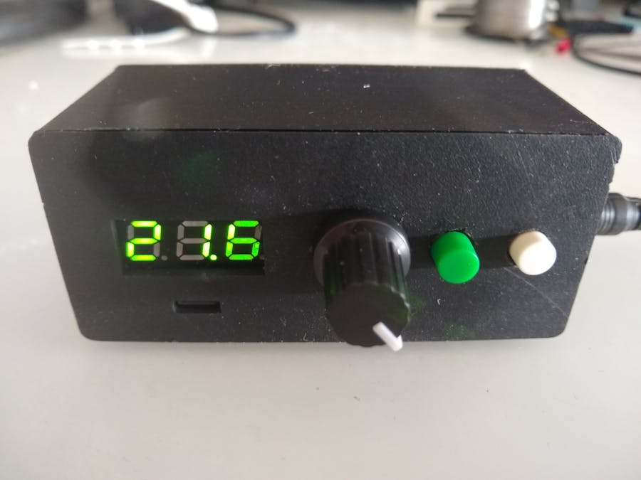
There are a number of Portable Power Supplies that makers have built around the cheap J5019 Adjustable Step Up module. Here are just a couple of them:
Portable Power Supply (18650 Battery) by alextrim
Portable Variable Power Supply by lonesoulsurfer
I decided to combine these two builds and design and 3D print a case for it.
Step 1 - Get the componentsThe components were sourced from eBay, AliExpress and Tada Electronics.
Step 2 - 3D print the caseThe STL files are included. Either take these to a 3D print shop or if you have your own printer, run them through your slicing software. I used a 0.2mm layer height with no supports.
Make sure the top fits snugly onto the bottom. You might need to do some filing if it is too tight.
Unless you 3D print using a raft (not recommended in this case), the first few layers on a heated print bed will tend to "flatten out". This means there is a small rim around each hole on the front panel. Using either a drill bit or sharp knife, take off this rim so the switches and potentiometer can clear the sides of their respective holes.
Step 3 - Add the front panel componentsAdd the switches, potentiometer and voltmeter to the front panel. Use a small amount of hot glue to hold the switches in place once you are happy with how far the button top extends out the front of the panel.
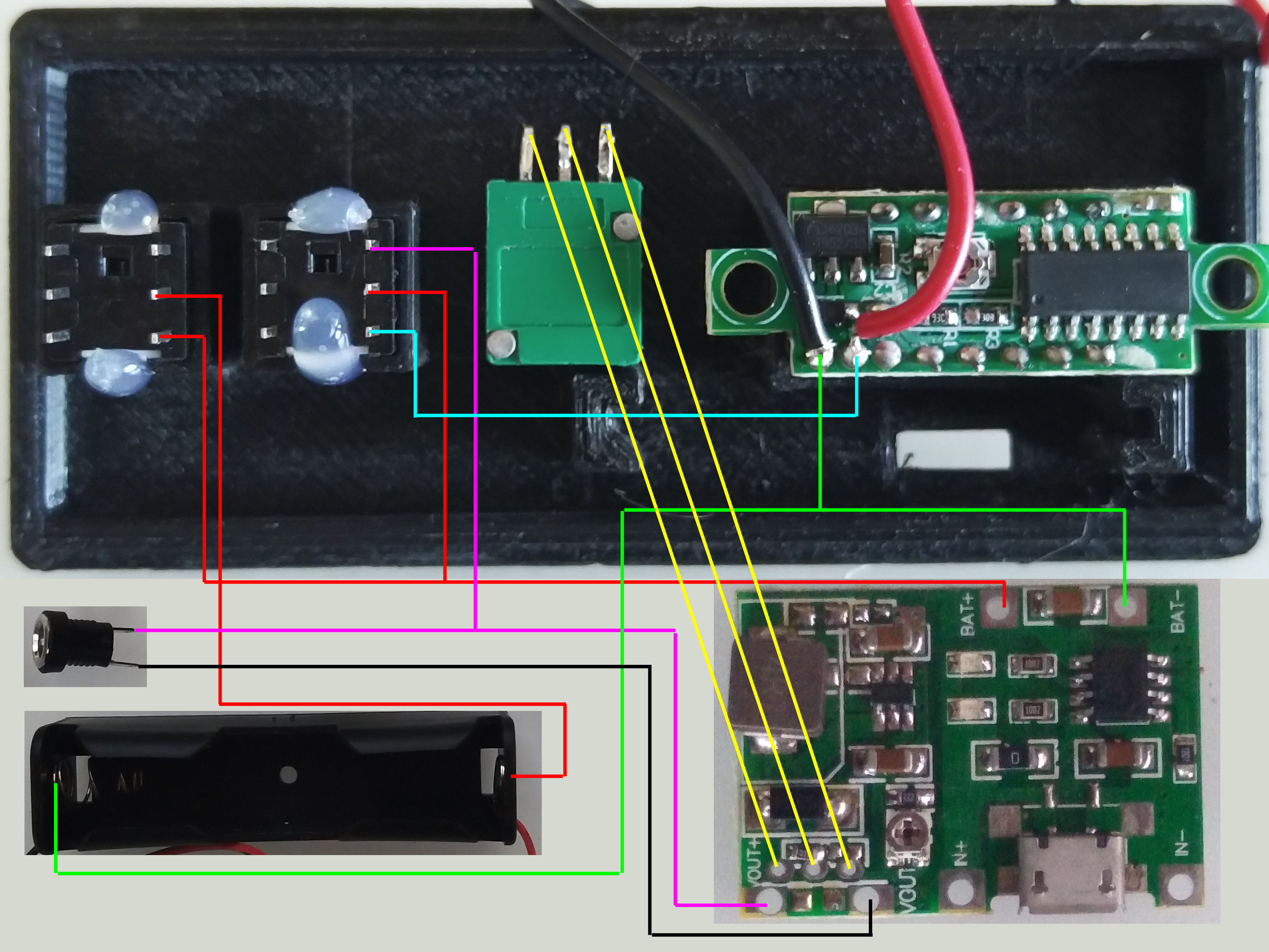
Next you need to wire up the components using the wiring diagram below. Don't wire the output power jack yet. Just leave the wires that will go to the output power jack sitting free for now.
The left switch (when viewed from the back) is the on/off switch while the right switch switches the voltmeter between measuring the output voltage or the battery voltage.
Step 5 - Insert the output power jack and batteryPlace the output power jack nut onto the two wires that will be soldered to the jack. Push the wires through the hole and solder onto the power jack. Place the power jack into the hole and screw on the nut as shown below.
Finally put in the battery holder with its battery. It should be a tight fit.
Step 6 - Make a lead for the outputAt this stage a lead for the output jack will be useful. I made a small cable with a DC power connector on one end and test clips on the other end. I took the lead off a faulty DC wall power brick and attached the test clips to the end that went into the power brick.
Before placing the module in its holder, test the unit. On the back of the voltmeter there is a small trim pot to adjust the voltage. Measure the output using a multimeter. Adjust the voltmeter so it reads the same voltage. While you may get it precise at one voltage, the cheap voltmeter may be out by a few millivolts at other values.
Originally I was using a 250K potentiometer to set the voltage. However I found that the whole voltage range was only adjustable in the last quarter of the rotation of the shaft. I replaced the 250K potentiometer with a 100K potentiometer and placed a 150K resistor in series with the left most pin of the pot when viewed in step 4.
Step 8 - Final assemblyOnce tested, put the module in its holder. You might have to use a small hammer to tap it in place. Make sure the OUT+ wire is not pinched by the rail. I designed the rail with a small bevel so the wire should have enough room.
My unit only goes down to 3.78 volts which is a bit of a shame since I do make projects that require a 3.3V supply. The voltage adjustment is too coarse and all adjustment is still close to the end of the potentiometers' travel. I think an antilog potentiometer would probably be more suited but I don't have any of these.
Overall it works and will be a nice addition to my toolbox. It is relatively compact and the J5019 module has the following specifications:
- Charging over Micro-USB.
- Output voltage: continuously adjustable 4.3-27V
- Charging current: up to 1A
- Discharge current: the maximum 2A
- Output reference maximum current: 5V 1.4A, 9V 0.8A, 12V 0.6A


Comments
Please log in or sign up to comment.