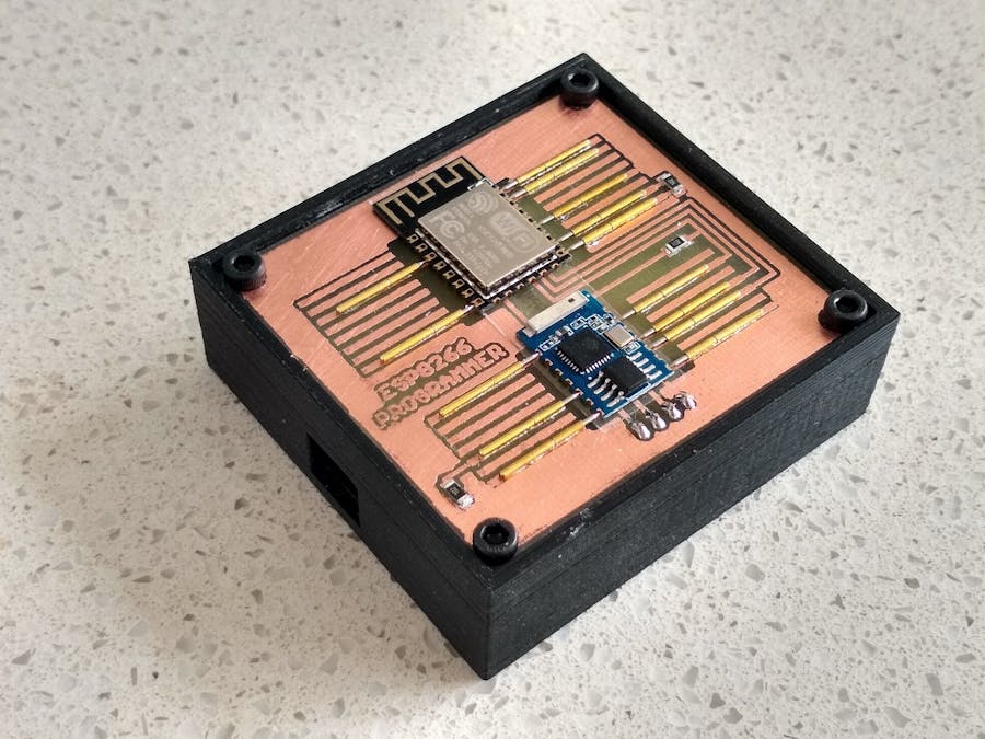
An improved version of this make is available at https://www.hackster.io/john-bradnam/esp-12-esp-03-development-kit-421631 It supports both programming and run modes and makes the GPIO pins available via a simple header so you can connect it to a breadboard.
The ESP-12 module is commonly found on WeMos D1 and NodeMCU boards to name a few. Boards like the WeMos provide extra functionality to the ESP-12 module such as a USB to serial converter, a 3.3V regulator and various LEDs to show what state the ESP-12 is in. If your build contains a limited amount of space, you can do away with these "extras" and place the ESP-12 or ESP-03 directly onto your build.
By using Pogo pins, these modules can be programmed without any need to solder pin headers etc.
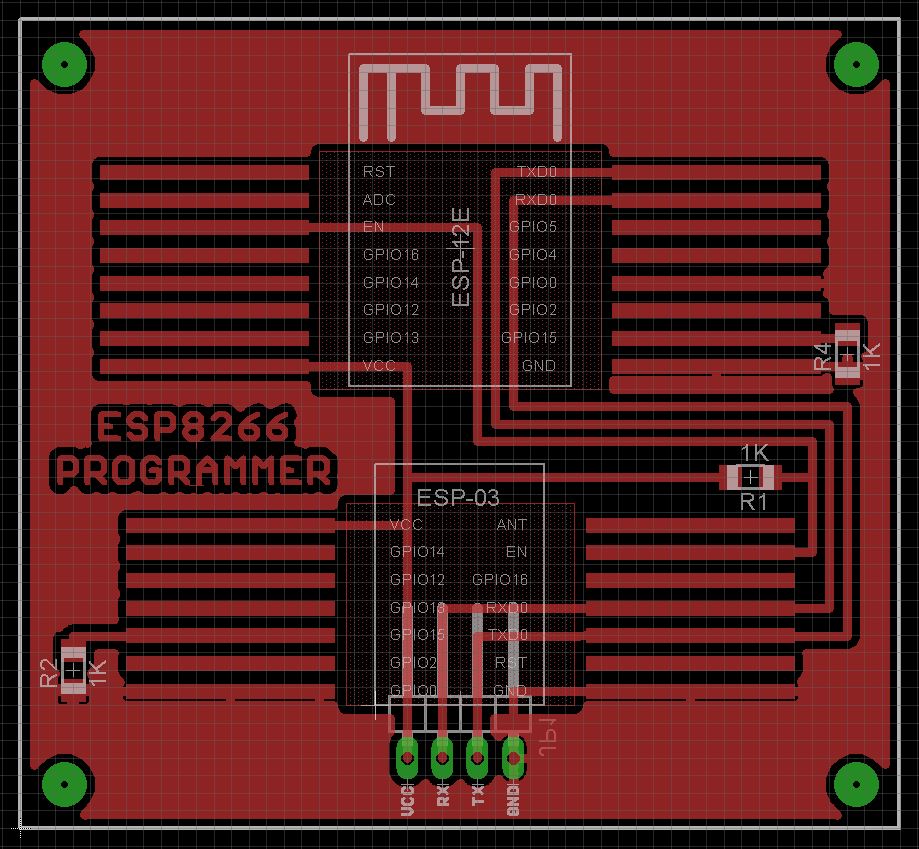
Making the PCBThe Eagle files have been included should you wish to have your board commercially made or do as I did and make it yourself. I used the Toner method. If you choose to make you own board, you need to add some insulation between where the ESP-12 and ESP-03 boards sits and the PCB itself. Usually the solder mask will provide this although it can get scratched so even if your board has a solder mask, it might pay to add more insulation. I used a small piece of transparent label. Unfortunately my attempt to print on the label sort of got rubbed off.
Pogo pins used are P75-B1 1.02mm spear ends. Pogo pins are very fragile and will bend easily. When picking them up with tweasers, don't press too hard or you will crimp them and they will no longer slide in and out easily anymore.
1. Get your tools ready
2. Apply solder paste
3. Position the pogo pin
4. Apply heat until the solder paste melts
Notes
Carefully solder each pin one at a time. I recommend you do one side first and measure where the pins should be soldered on the other side based on the amount of pressure you want on the connections. You don't need a lot of pressure on each connection. Too much pressure will mean it will be hard to insert the module.
Making the caseThe STL file is included so you can print the case or get it printed from a 3D print shop. Once printed, drill out the corner holes with a 2.5mm drill and create a thread with a 3mm tap. Use M3 6mm screws to hold the board in place.
Hot glue the FTDI programming board in place. Make sure you set the FTDI board to 3.3V.
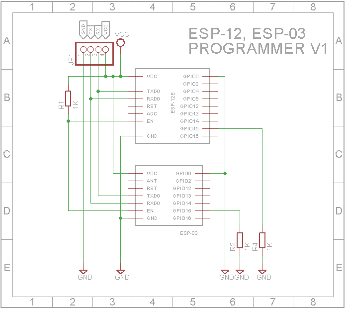
Wire it to the PCB. See Schematic for connections.
Arduino IDEIf you haven't already done so, you need to install the drivers and board definitions. For a description on how to do this, see the following link:
Programming the ESP8266 WeMos-D1R2 Using Arduino Software/IDE
To program your ESP-12 or ESP03 (do not try and program both at the same time), connect a USB cable to your PC. In the Arduino IDE, select the board to be "Generic ESP8266 Module" and the programmer to be "AVR ISP".
The ESP-12 or ESP-03 modules will always be in programming mode when using this programmer. (GPIO0 is always held LOW).


_3u05Tpwasz.png?auto=compress%2Cformat&w=40&h=40&fit=fillmax&bg=fff&dpr=2)
Comments