


Hardware components | ||||||
| × | 60 | ||||
| × | 1 | ||||
| × | 1 | ||||
| × | 2 | ||||
| × | 1 | ||||
| × | 1 | ||||
| × | 1 | ||||
 |
| × | 1 | |||
| × | 1 | ||||
Hand tools and fabrication machines | ||||||
 |
| |||||
This is my build of Led Panel - Panneau à Led by HelioxLab and incorporates a dimmer circuit to control the light intensity of the lamp.
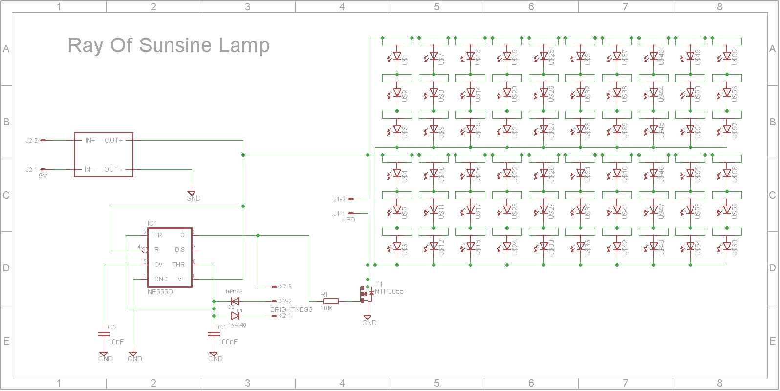
SchematicThe dimmer circuit generates a PWM signal that drives a N-Channel Power MOSFET. It is built around a 555 timer.
555 Trigger Pin
Pin 2 is the trigger pin. The trigger sets the output pin (pin 3) high when the voltage on pin 2 drops to below 1/3 of the supply voltage.
555 Threshold Pin
Pin 6 is the threshold pin. The threshold sets the output pin (pin 3) low when the voltage on pin 6 reaches 2/3 of the supply voltage.
Charging and discharging cycle
The slider potentiometer varies the charge and discharge rate of the capacitor C1.
When the output pin of the 555 timer (pin 3) is high, the capacitor charges through one side of the potentiometer via D2. When the output pin of the 555 timer is low, the capacitor discharges through the other side of the potentiometer via D1. This means that the potentiometer doesn't impact the frequency of the output signal but does change the mark/space ratio (the ON time of the output pin compared to it's OFF time).
The output pin drives a N-Channel Power MOSFET which in turn controls all the LEDs. The frequency of the 555 circuit is around 1kHz.
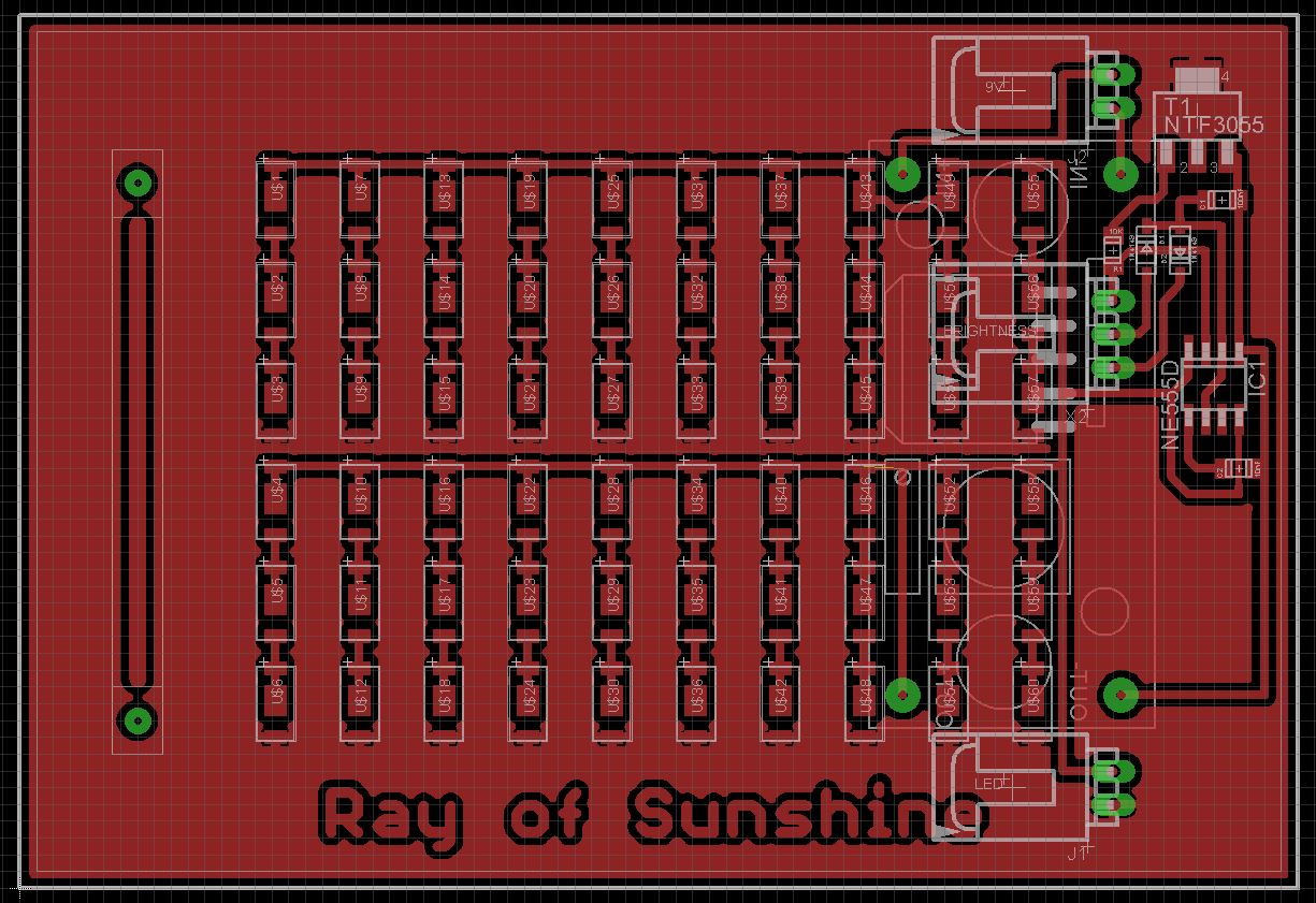
Assembly - Step 1The Eagle files have been included should you wish to have the board commercially made or you can do as I did and make it yourself. I used the Toner method.
Start by adding the SMD components. I find it easier to use solder paste rather than use solder from a reel when soldering SMD components. For this project I recommend using a hot-plate or oven to melt the solder. Some PCB manufacturers will add the SMD components for you for an extra cost.
The 10K slider pot is screwed to the board using M2 screws. Wire the pot such that the top pin goes to X2-2 pin on the schematic, the slider pin to X2-3 and the bottom pin to X2-1.
Add the DC-DC buck convertor after setting the output voltage to 9V to the back of the board. I have used many of these in the past and so far have encountered at least 3 variations of board that have different hole spacing. Hopefully if you make this, you get the variant that I designed the PCB for. If not you might have to hot glue it to the back and run wires from it to the board.
Optionally add K2510 2-Pin header to the board if you don't want to solder the power wires directly to the PCB.
Glue the PCB into the case using hot glue.
Hot glue the battery holder to the case's back. I used three single 18650 battery holders because that is what I had on hand at the time. It is easier to use a triple 18650 battery holder.
I also hot-glued a K2510 2-Pin header so I could unplug the back but this is optional. The wires go to the PCB via the on/off switch.
Everything fits well. Thankyou HelioxLab for a fantastic design. Beau travail!
As my eyesight has slowly degraded over the years, I have found this lamp extremely useful to light up those hard-to-see areas.

Comments
Please log in or sign up to comment.