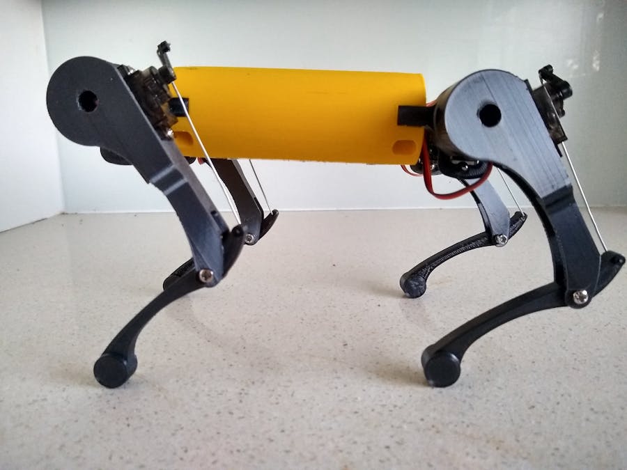
This is my redesign of Robot Dog boston by ArduinoChan and published on Thingiverse.
The project uses software by Gleb Devyatkin. This code is designed for a leg that uses 3 servos. These servos are named Alpha, Beta and Gamma. The Alpha servo is for lifting the whole leg outwards. The Beta servo is the hip joint and the Gamma servo is the knee joint. This robot only uses Beta and Gamma.
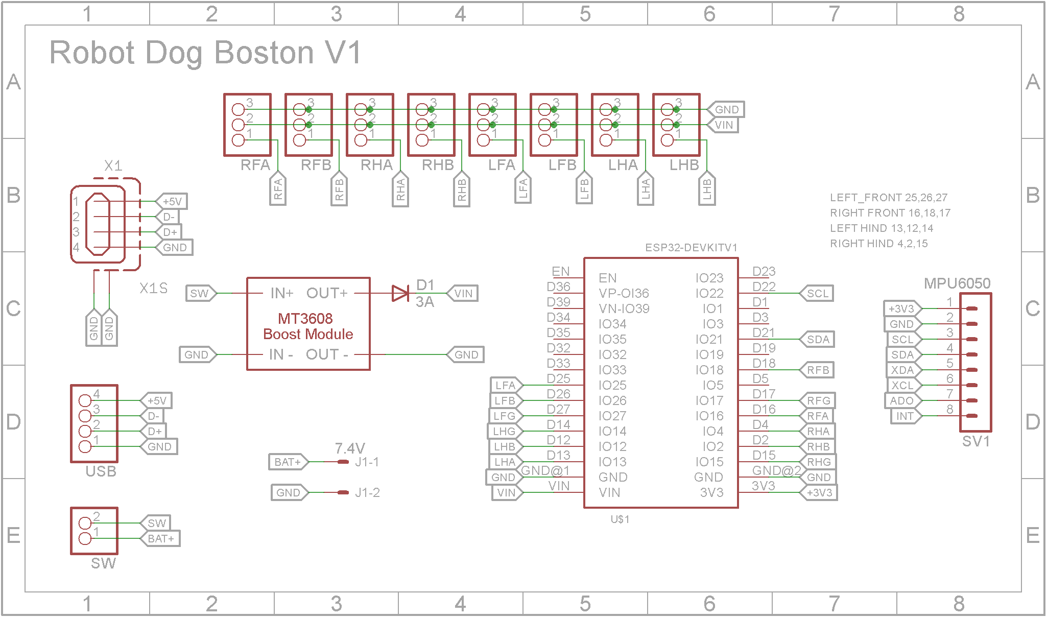
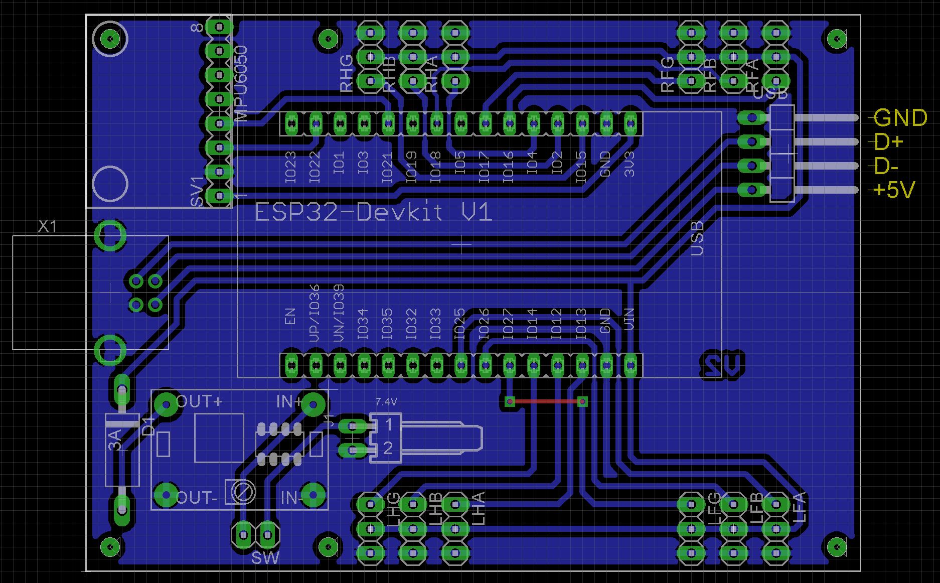
Unfortunately it was only when I went to program the dog that I realized that I designed the board for the Alpha and Beta servos instead of the Beta and Gamma servos. This means I had to update the config_small.h to transpose the pins assigned to these servos. More on that later.
3D printingOne of the changes that I made was to use screws for the joints and fixtures rather than using filament. Also I wanted to "clean" up the body by printing it more or less as a single piece. I designed an opening in the bottom of the body to hold the battery pack and provide access to the electronics.
Rotate the body 180 degrees on the build plate so the opening is at the top and print with supports. The Body_lid is printed without supports. The Body requires four M3 x 4mm Long x 4mm OD inserts to be pressed into each tab.
Also add two M2.5 x 3mm Long x 3.5mm OD inserts into Body_Lid and screw on the dual 18650 battery holder using M2.5 x 4mm screws. The lid is secured to the body using four M3 countersunk (flat head) 6mm screws.
There are 8 holes that secure the hips to the body. Use a 3mm tap to create a thread for the 20mm M3 screws that are used to secure the hips to the body. When printing the hips, you need two of HipLeft and two of HipRight. The same applies to HamLeft and HamRight.
I didn't change the shank so you need to drill out the hole that connects to the ham using a 3mm drill. Connect the shank to the ham using a M3 screw with a lock nut. Don't tighten it too tight. The shank should rotate freely without any lateral play.
The tendons were created by unfolding mid-sized paper clips. They are held in place using the 3D printed pins.
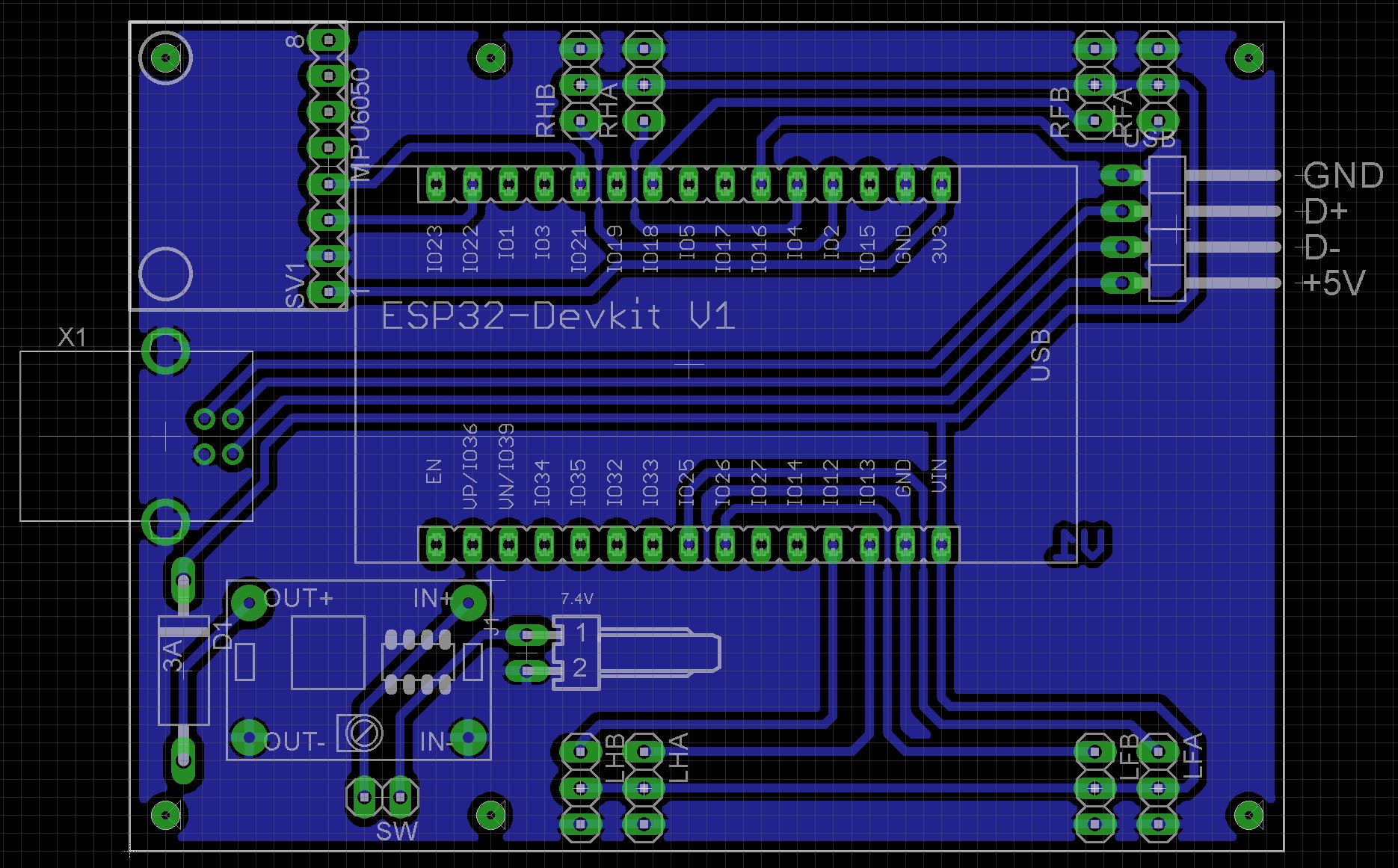
When designing the PCB, I choose to use a USB Type B socket rather than try to make the mini USB on the ESP32 Development Board accessible through the case. USB Type B sockets can take a lot more punishment than mini USB sockets surface mounted to a PCB. I cut up a old mini USB cable and added a 4 pin Dupont connecter to the end so that it can be plugged into the PCB.
Make sure you set the DC-DC regulator to output 5V before you attach it to the PCB. The PCB is held in place using four M2 x 4mm screws.
The Eagle files have been included should you wish to have the board commercially made or you can do as I did and make it yourself. I used the Toner method.
SoftwareThe code is "Off the shelf" software downloadable from GitHub. Because of my mistake getting the servos connections wrong, you will need to modify config_small.h first. Lines 37, 57, 77 and 97 contain the ESP32 pins that the Alpha, Beta and Gamma servos are connected to respectively. You need to swap the 1st and 3rd numbers for each of the legs.
There is code to access a INA219 current sensing board but it isn't used so I didn't bother adding it to my redesign.
ConclusionAn enjoyable build on my part, I hope you find this useful.
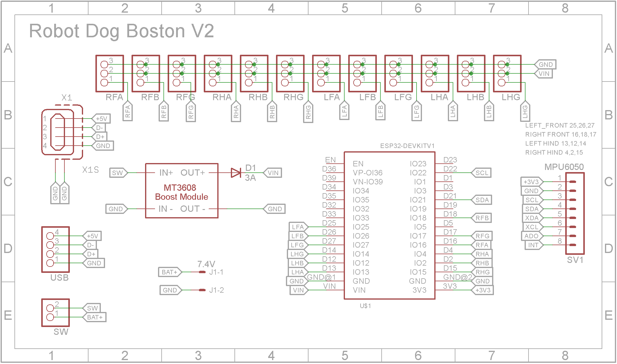
Update V2The Schematic and PCB have been updated to provide headers for all three servos for each leg. Plug the Hip servos into the LFB, RFB, LHB and RHB headers and the Knee servos into the LFG, RFG, LHG and RHG headers. The LFA, RFA, LHA and RHA are not used. There is no longer a need to modify the config_small.h file.






Comments
Please log in or sign up to comment.