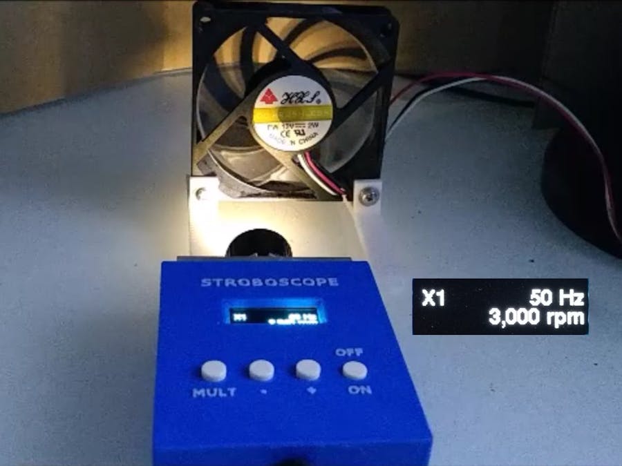
Stroboscope is a flashing light that can provide light pulses at a variable rate. When a rotating object is observed in a powerful beam of pulsed light with the frequency of that pulsed light matching the rotations per second of the rotating object, the rotating object appears stationary.
This allows the speed of any rotating object to be calculated by varying the pulse rate until the rotating object appears stationary. Once this state is achieved, revolutions per minute (rpm) of the rotating object can be calculated from the frequency of the pulsed light.
If the object appears to be stationary when the pulsed light is at a frequency of 50Hz or 50 times a second, the object is rotating at 3,000 rpm (50 x 60).
DemonstrationOperationThe ON/OFF switch switches on or off the LED (it is not a power switch for the unit).
The MULT switch switches between the multipliers x1, x10 and x100. It determines the amount of change that the + and - buttons have on the frequency.
The + switch increases the frequency by the selected multiplier up to a maximum of 500 Hz or 30,000rpm.
The - switch decreases the frequency by the selected multiplier down to a minimum of 1 Hz or 60rpm.
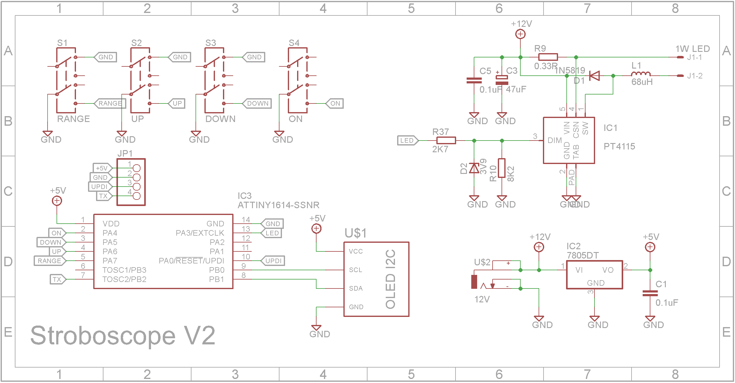
DesignThe circuit is built around a PT4115E LED driver. It contains an inductive step-down converter to power the LED at a predetermined current. It has a maximum switching frequency of 1MHz.
The PT4115E drives a 1W white LED and you can easily use a 3W or 5W LED instead. See the PT4115E datasheet as you will need to change the current sense resistor to allow more current to flow in the LED. (Iout = 0.1 / Rs)
The microprocessor is a ATtiny1614. It as 16k of flash and 2k of RAM. It also drives a 128x32 OLED screen to display the current output.
All files are printed with a 0.2mm layer height and no supports.
When printing "Strobe - Text.stl", change to a contrasting filament at the start of layer 4. Using double-sided tape or glue, attach the "Strobe - Text.stl" part to the "Strobe - Front.stl" part.
Drill out the PCB mount holes with a 2.5mm drill and create a thread with a 3mm tap. The PCB is held in place using four 6mm M3 screws.
The LED assemblyThe 1W or 3W LED comes on a small star shaped heatsink. You can also purchase lens units for these LEDs on sites like eBay, AliExpress etc. The angle of light they are designed to project varies. Get the narrowest angle you can find.
Search for "10pcs 5 15 30 45 60 90 120 Degree Angle LED Lens w/20mm Holder Flat Transparent Lens Reflector for 1W 3W High Power LED Emitter" on AliExpress.
Cut the 20mm x 6mm aluminum excursion to a length of 53mm. Drill two 3mm holes 16mm either side of center and two 2mm holes 8.5mm either side of center. Both sets of holes should be 5.5mm down from the top edge.
Solder a positive (anode) lead and a negative (cathode) lead to the star LED. Feed the wires through the smaller holes and use thermal paste to glue the star LED to the middle of the aluminum excursion.
Next glue the lens to the star LED using super glue. Fix the whole assembly to the case using two 12mm M3 screws with nuts.
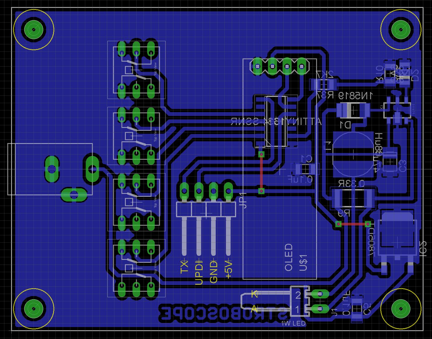
Due to the fact that the ATtiny1614 and PT4115E only come in SMD packages, the board has been designed to use Surface Mount Devices (SMD) where possible.
The Eagle files have been included should you wish to have the board commercially made or you can do as I did and make it yourself. I used the Toner method.
Assembly - Step 1Start by adding the SMD components. I find it easier to use solder paste rather than use solder from a reel when soldering SMD components. I used my SMD Reflow Hot Plate to reflow the solder paste.
Add the links if your board is single-sided.
Add a 4 pin right angle low height male pin header to the copper side of the board for the UPDI programmer. I like to dab a bit of paint on the pin header to show what the pins are so I don't connect the UPDI programmer incorrectly and blow up the ATtiny1614.
On the component side, add a polarized right-angle header for the LED connection.
Add a 4-pin straight female pin header for the OLED display. You must use a 6mm high pin header and not the standard 8.5mm high pin header.
Add the four 8mm x 8mm switches. The top switch as shown below is a latched on/off switch where as the other 3 are momentary switches.
Add the DC power socket.
Add the switch caps and screw the PCB into the case using four 6mm M3 screws.
Before you put on the back, program the ATtiny1614 microprocessor (see next section).
The ATtiny1614 is part of the new breed of ATtiny microprocessors. Unlike the earlier series such as the ATtiny85, the new breed use the RESET pin to program the CPU. To program it you need a UPDI programmer. I made one using a Arduino Nano. You can find complete build instructions at Create Your Own UPDI Programmer. It also contains the instructions for adding the megaTinyCore boards to your IDE.
ConclusionThe heatsink for the LED is probably a bit of over-kill. The Stroboscope provides reasonable accuracy when measuring rotating objects so all-in-all a useful project.


Comments
Please log in or sign up to comment.