Recently overlok, a fellow Hackster.io user asked if I had any plans to design a alarm clock that used a TM1637 display and used a rotary encoder to set the time and alarm. I found the idea of a rotary encoder intriguing and wondered how this could be implemented from a design and user-interface point-of-view.
This is the design that I came up with. It is a tubular alarm clock with a speaker at one end and the rotary encoder embedded at the other end.
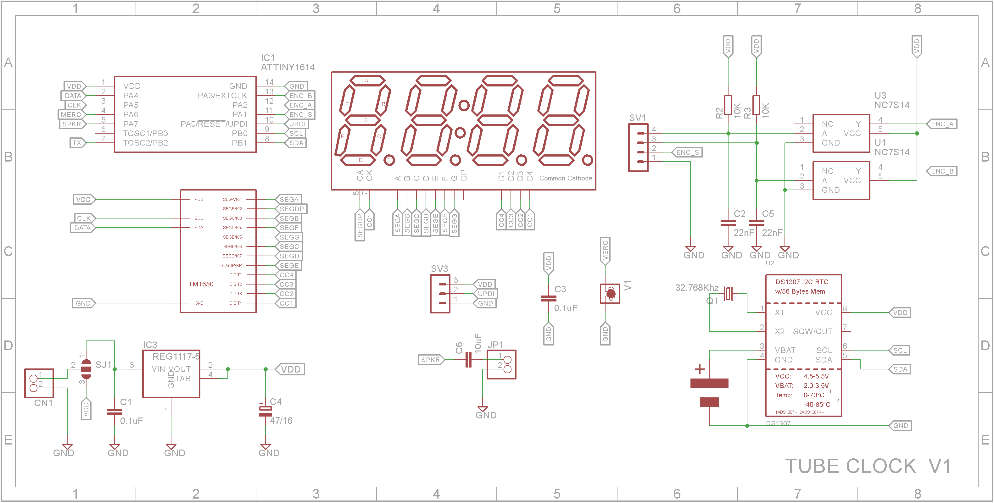
DesignThe design of this clock leveraged heavily on my Folding clock that I made earlier. The display is a 0.8in 4-Digit 7-Segment display driven by a 4-Digit 7-Segment display driver (TM1650). The microprocessor is a Microchip ATtiny1614 and the time is controlled by a Real Time Clock chip (DS1307) with its own battery so as to not lose any time when the main power supply is disconnected.
The rotary encoder contains two sets of contacts which can become quite noisy resulting in incorrect readings. I added a RC network and Schmitt trigger between each contact and microprocessor. This removes any noise generated by the contacts and provides clean switch change signals to the microprocessor.
Setting the timeThe clock is configured using a rotary encoder that sits in one end of the clock. Pressing the rotary encoder knob will switch the clock through its setup modes. These are as follows:
A on - Shows alarm is on. Rotating the rotary knob counter-clockwise will turn off the alarm.
AoFF - Shows alarm is off. Rotating the rotary knob clockwise will turn on the alarm.
Ahxx - Shows the current alarm hours. Rotating the rotary knob clockwise will increase the hours, rotating the rotary knob counter-clockwise decrease the hours.
Anxx - Shows the current alarm minutes. Rotating the rotary knob clockwise will increase the minutes, rotating the rotary knob counter-clockwise decrease the minutes.
thxx - Shows the current time hours. Rotating the rotary knob clockwise will increase the hours, rotating the rotary knob counter-clockwise decrease the hours.
tnxx - Shows the current time minutes. Rotating the rotary knob clockwise will increase the minutes, rotating the rotary knob counter-clockwise decrease the minutes.
Any changes are written back to the RTC and/or EEPROM.
3D printingThe STL files are included. Either take these to a 3D print shop or if you have your own printer, run them through your slicing software. I used a 0.2mm layer height.
I printed the main body with a raft and supports touching the build plate. I made sure that the back side of the clock was the closest to the build plate.
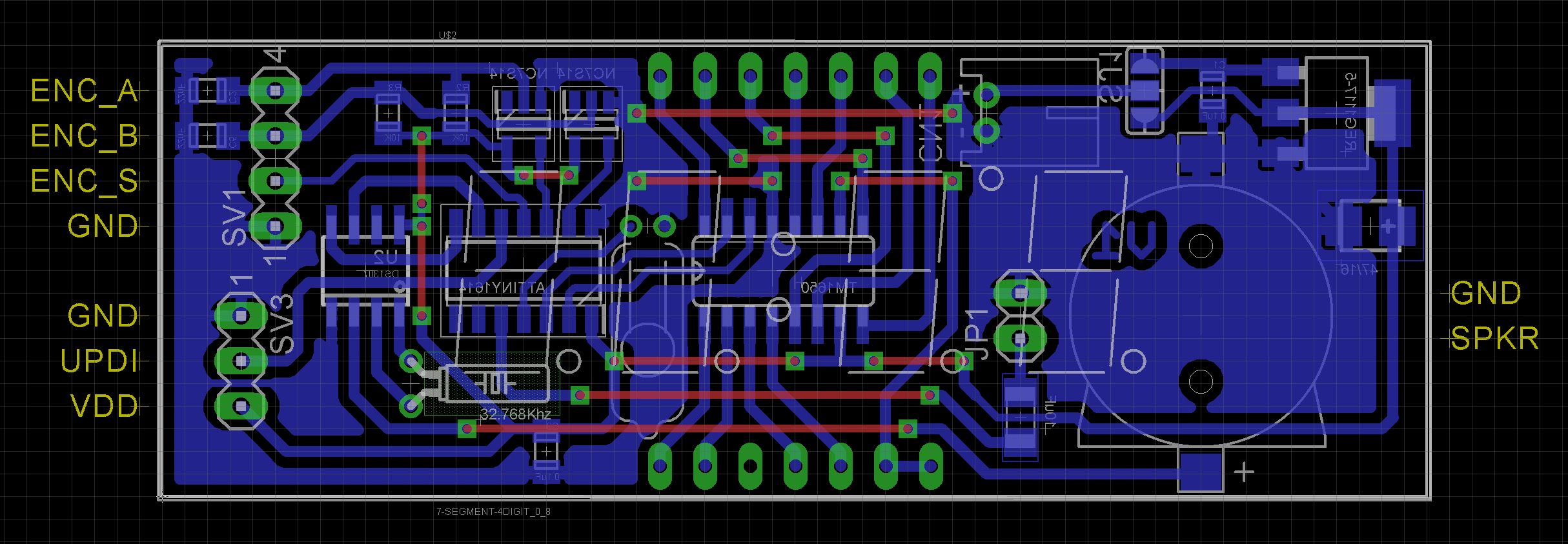
The PCBTo minimize the space required, the board has been designed to use Surface Mount Devices (SMD) where possible. Also the board are designed to be the same size as the 0.8in 4-Digit 7-Segment displays.
When designing the board, I didn't map the segment pins to their corresponding display pin but rather kept the layout as simple as possible and adjusted for it in the software.
The Eagle files have been included should you wish to have the board commercially made or you can do as I did and make it yourself. I used the Toner method.
Assembly - Step 1Start by adding the SMD components. I find it easier to use solder paste rather than use solder from a reel when soldering SMD components. Leave the battery holder off for the time being.
Add the links if you are using a single sided board.
My initial plan was to have it run from a 18650 battery or via a power brick. Unfortunately it was only after I made the PCB that I realized that the DS1307 requires a minimum of 4.5V to operate correctly. I should of used a DS1302 as this can operate down to 2.7V. Anyway, you need to add a solder bridge so that the power socket is connected to the 5V regulator.
Add the UPDI, speaker and rotary encoder pin headers and the power socket
Note: I usually dab a bit of paint on my connectors to show the correct orientation for any connections that might be made to them.
Assembly - Step 4Initially I planned to use a vibration switch so that you could tap the clock to switch off the alarm. However I couldn't get this to work as intended so I replaced the vibration switch with a mercury switch and modified the software so the display showed the time in the correct orientation even when the clock was upside-down. This has the added bonus of supporting both left and right handed users. Add a mercury switch instead of the vibration switch that is shown in the photo below.
Before adding the 32.768Khz watch crystal for the RTC, wrap it in some Kapton tape before soldering it on the copper side of the board. This will ensure that it doesn't short out any tracks underneath.
Add the display to the board. (Make sure you don't solder the display in upside down!)
Wire up the rotary encoder and buzzer to their respective female pin headers. Add the buzzer and rotary encoder to the case.
Wire up the DC power socket to a JST plug and add it to the back panel.
Place the board into the case and plug in the cables you made in the last step. If the display is loose, you can use some hot glue to hold the board in the case
The ATtiny1614 is part of the new breed of ATtiny microprocessors. Unlike the earlier series such as the ATtiny85, the new breed use the RESET pin to program the CPU. To program it you need a UPDI programmer. I made one using a Arduino Nano. You can find complete build instructions at Create Your Own UPDI Programmer. It also contains the instructions for adding the megaTinyCore boards to your IDE.
Connect the UPDI programmer
Once the board has been installed in the IDE, select it from the Tools menu.
Select board, chip (ATtiny1614), clock speed (20MHz) and the COM port that the Arduino Nano is connected to.
The Programmer needs to be set to jtag2updi (megaTinyCore).
Open the sketch and upload it to the ATtiny1614.
ConclusionOverall an interesting project that turned out better than I thought it would. Thanks overlok for the inspiration 😃


Comments
Please log in or sign up to comment.