


Hardware components | ||||||
| × | 1 | ||||
| × | 1 | ||||
 |
| × | 1 | |||
 |
| × | 1 | |||
| × | 1 | ||||
Today microprocessors tend to dominate many of the electronic projects that are built today. They reduce component counts and are becoming even more versatile. Even the new tinyAVR® microprocessors now have programmable user circuits built in. 40 years ago when microprocessors were limited and quite expensive, many projects involved a number of discrete components and basic integrated circuits.
Going back through an archive of old electronic magazines, the following "Wheel of fortune" circuit looked an interesting build.
At first the circuit might seem quite complicated, but if you break it down into its logical parts, it is actually quite simple.
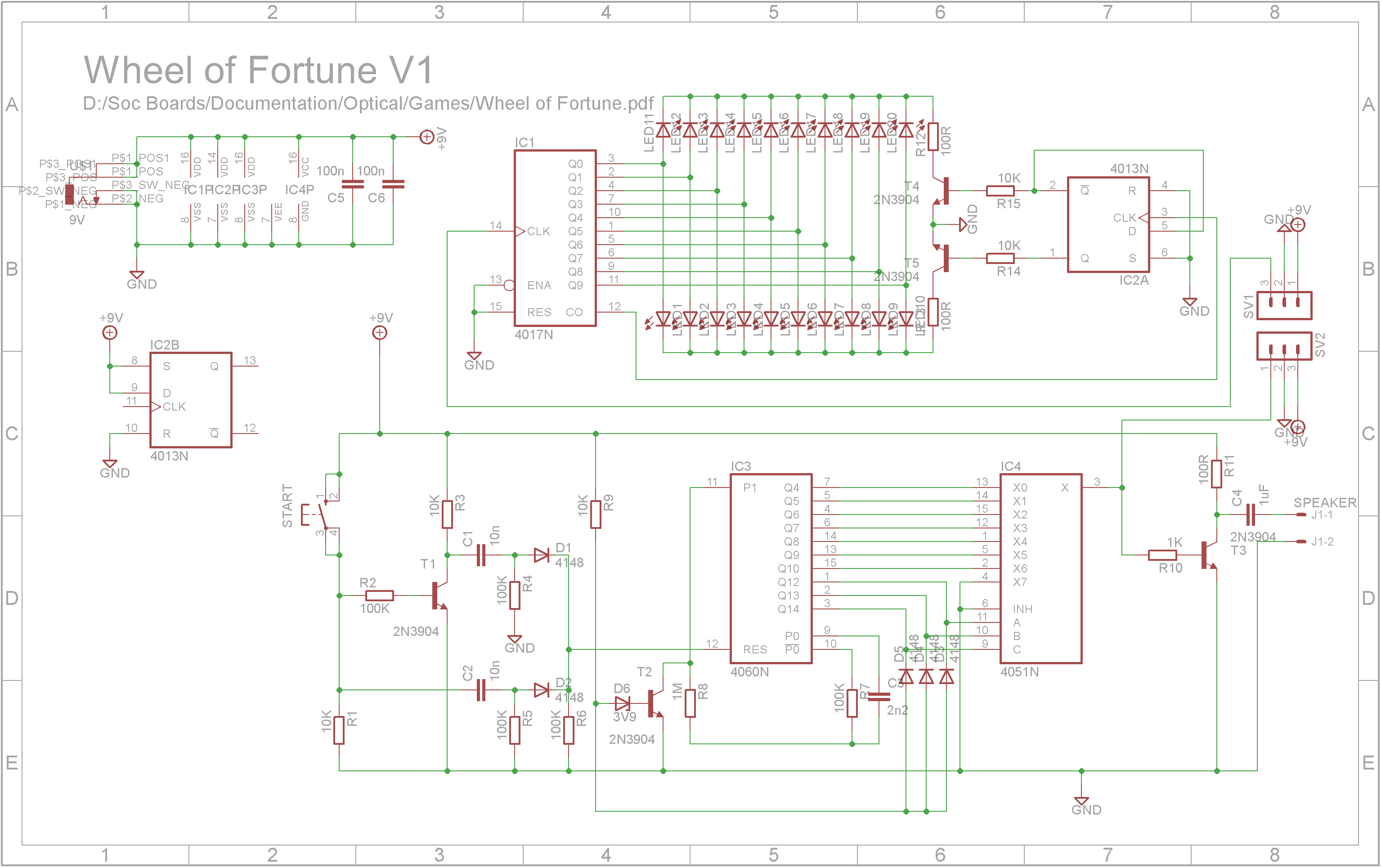
Starting with the LED display, 20 LEDs are cycled by a single 4017 (IC1) decade counter. When a clock is feed into pin 14 of 4017, Q0 to Q9 sequentially go HIGH on each clock cycle. After 10 clock cycles, the counter starts over again. At this point, the CO (carry out - pin 12) toggles a Flip-Flop (IC2 4013) wired to toggle states on each CO signal. The outputs of the Flip-Flop drive transistors that tie each group of 10 LED cathodes to ground via a 100 ohm resistor (current limiting for the LEDs). When the Q output (pin 1 on 4013) is HIGH, ~Q output is LOW (pin 2). This switches T5 on enabling LED 1 to LED 10 and switches T4 off disabling LED 11 to LED 20. When the Flip-Flop is toggled, Q output goes LOW and ~Q output goes HIGH. This switches T5 off disabling LED 1 to LED 10 and switches T4 on enabling LED 11 to LED 20.
The 4060 (IC3) contains an oscillator and a number of dividers.
R8, R7 and C3 determine the frequency of oscillation. When transistor T2 is on, it shorts P1 (pin 11) to ground and this causes the oscillator to stop running. Diodes D3, D4 and D5 act as a 3-Input AND gate. The transistor switches on when the outputs Q12, Q13 and Q14 all go HIGH thus stopping the oscillator.
The oscillator has a frequency of around 2048Hz. Q4 which is the divide by 16 output has a frequency of 128Hz, Q5 which is the divide by 32 output has a frequency of 64Hz, Q6 - 32Hz, Q7 - 16Hz, Q8 - 8Hz and so on. Q10 is 2Hz, Q12 is 0.5Hz, Q13 is 0.25Hz, Q14 = 0.125Hz.
The 4051 is a 8 channel multiplexer. Think of it as a 1 pole 8 way rotary switch where the A, B, C binary inputs select which output (X0 to X7) is connected to X (pin 3). When Q12, Q13, Q14 is low, the OUT pin or clock that drives the counter for the LED displays connects to Q4 and thus runs at 128Hz. After 0.5 seconds, Q12 goes HIGH and the multiplexer OUT pin is connected to Q5 and thus runs at 64Hz. Another 0.5 seconds later, Q12 goes LOW again and Q13 goes HIGH. This causes the OUT pin to be connected to Q6 and this runs at 32Hz. This continues until the OUT is Q10 and is running at 2Hz. Finally Q12, Q13, Q14 will all become HIGH at which point T2 switches on and the oscillator stops.
By applying a RESET signal to IC3 once it has stopped, the wheel will spin again. However the time period for the whole cycle is constant. This means the lights will circulate a fixed amount of rotations on every spin. There is no random element to ensure every spin uses a different time period.
The only random component is the user themselves. When we press and release a button, every time the period of the press will be different (maybe by a few milliseconds but different nonetheless). Using this, the switch will apply two reset pulses, one when the button is pressed and the other when the button is released. Because the display counter (the 4017) is not reset, it will count at a rate of 128Hz while the button is being pressed. This will ensure that when the second RESET occurs when the button is released, it starts at a completely random LED.
When the button is pressed, C2 will effectively be a short circuit until it charges up. This gives a pulse to RESET line via D2. In the meantime, T1 switches on and shorts one side of C1 to ground causing C1 to discharge through R4.
When the button is released, the T1 switches off and C1 being fully discharged will effectively be a short circuit until it charges up. This gives a pulse to the RESET line via D1. In the meantime, C2 is discharged through R1 and R5.
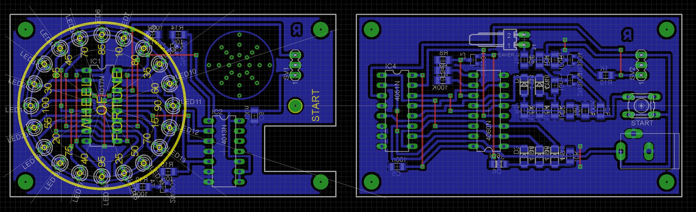
BuildI have a number of cheap 85mmx50mmx20mm cases which I bought a while ago on eBay. They were less than a $1 each. To fit this circuit into the box, a number of SMD (surface mount devices) components are used.
The Eagle files for the PCB have been included should you wish to get them commercially made or you can choose to make them yourself.
I used the Toner method to make mine.
Discreet electronics without microprocessors is still fun. It's a pity in some-ways that it is a dying art but if you are interested in looking at old electronic magazines, the best source that I have found is https://worldradiohistory.com/


Comments
Please log in or sign up to comment.