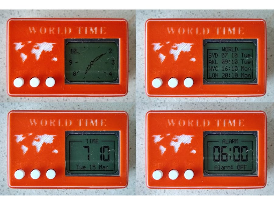
This small battery powered clock can be configured to display as a analog clock, digital clock, world clock or as a digital alarm clock. This clock is similar to the Nokia Analog Digital Alarm Clock that I built a few years back. It used a ATtiny1614 microprocessor (16k Flash, 2k Ram). Unfortunately it didn't have sufficient Flash memory to hold all of the feature set. This time I used a ATtiny3216 microprocessor. This has twice the Flash memory and it allowed me not only to incorporate the previous feature set but to add the current time in selectable cities around the world. It automatically adjusts for daylight saving that maybe active in any of the selected cities.
Building the caseUsing the STL files provided, print the front and the back. I used a 0.2mm layer height and no supports. When printing the front, do the first 2 layers in your chosen color, change to a contrasting color at the start of layer 3 and switch back to the chosen color at the start of layer 5.
There are two mounts in the front to support the printed circuit board. Drill these out with a 2.5mm drill and create a thread with a 3mm tap.
Building the electronicsOne of the issues I ran into was the different variants of Nokia 5110 displays.
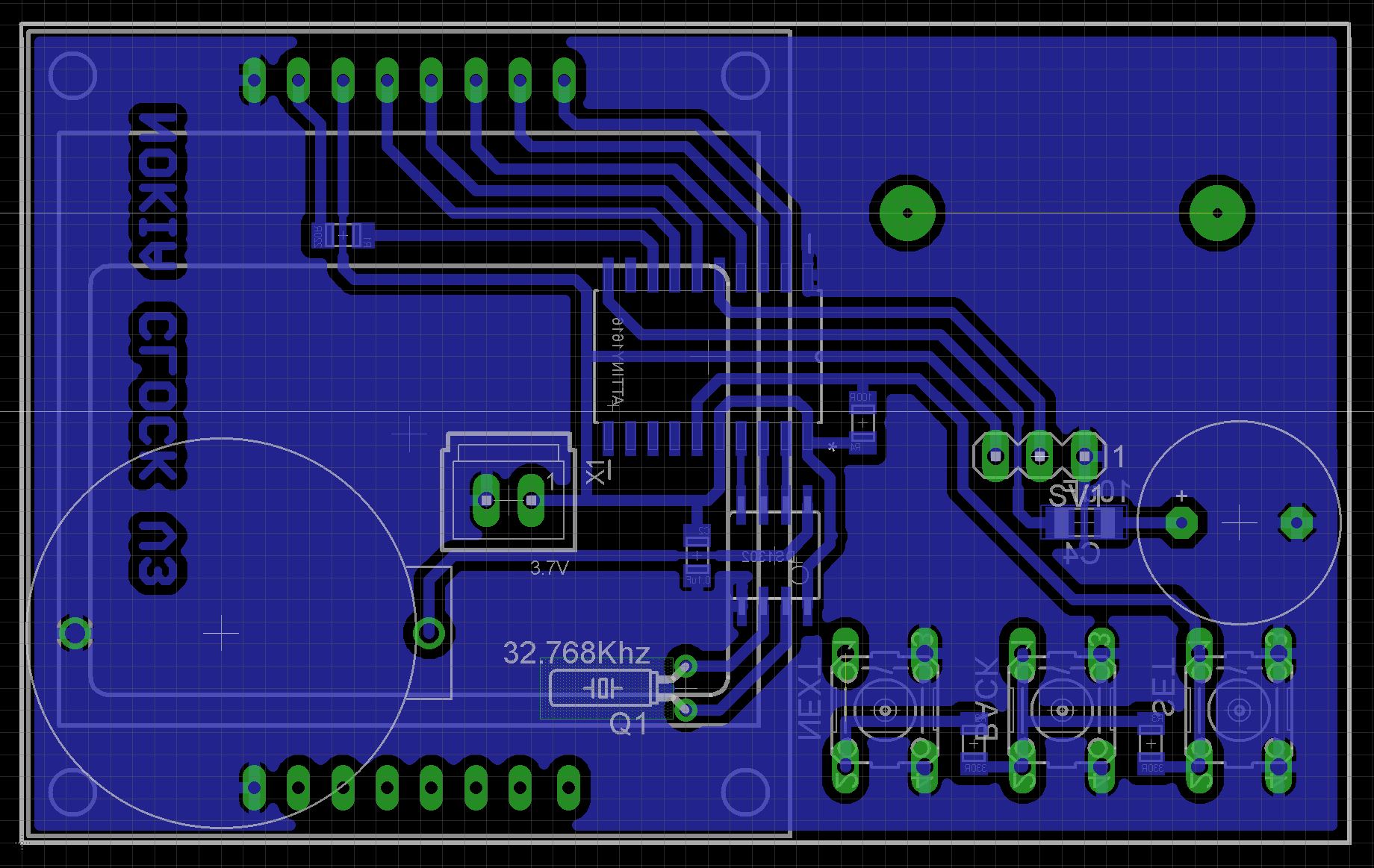
The PCB is designed for the middle variant. The headers on the middle variant are wider (designed to fit on a 0.1in grid) and the right hand variant only has a single header row.
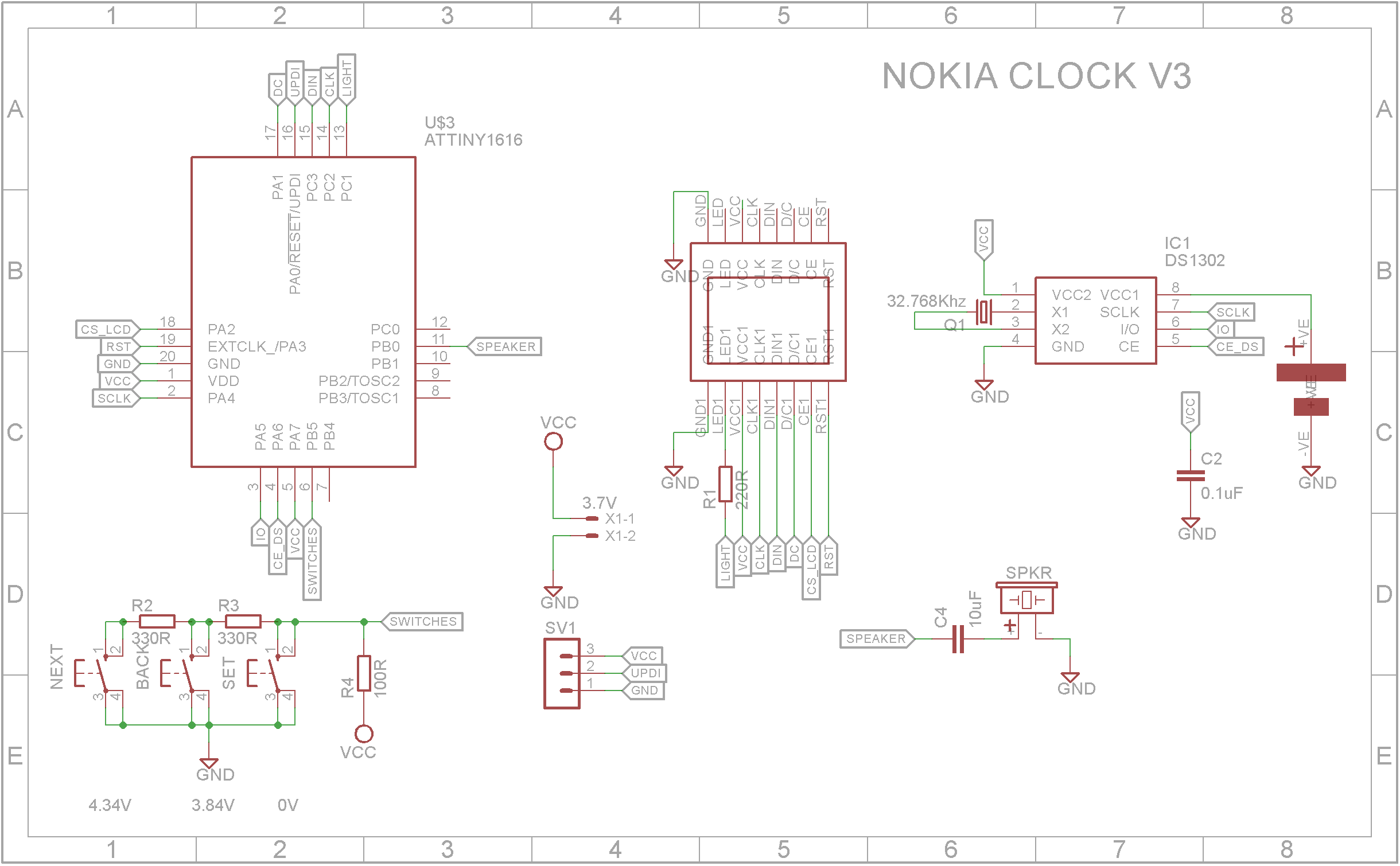
The Eagle files have been included should you wish to get the board commercially made or you can make it yourself. I used the Toner method to make mine.
Start by adding the SMD components. I find it easier to use solder paste rather than use solder from a reel when soldering SMD components.
Add the machine header onto the copper side of the board.
Next add the top side components. I suggest you glue the button tops to the tactile switches first before mounting the to the board. Don't let the glue run down the shaft and into the switch. Place the button tops face down on the bench, add some super glue in the shaft hole and put the switch shaft in the hole. Keep it sitting upside down until the glue dries.
The 18650 battery holder sits over the PCB mounting holes. Stick the holder down with double sided tape. Drill through the two 3mm mount holes from the copper side of the PCB and through the plastic of the battery holder. Use a 10mm drill to countersink the holes in the battery holder.
Cut and solder the 18650 battery holder leads to the board.
Add the male machine headers to the LCD and plug into PCB. Screw the PCB into case.
The ATtiny3216 processor is part of a new breed of microprocessors from Microchip. Please read my tutorial on how to program these processors.
You will need to download and install the LCD5110_Graph library into the Arduino IDE. Also you will need the DS1302RTC library as well.
Setting up the world time tableIn the file World.h, there is a table starting on line 63 that defines what cities / time zones can be selected. It is terminated by two NULL pointers. This allows you to add as many cities / time zones you deem necessary.
Each entry in the table has three elements. The first is a 3 character name that represents the city or time zone. The second is a pointer to the rule which determines when daylight saving starts. The & character just means "the address of". The third is a pointer to the rule which determines when daylight saving finishes.
RULE worldChoices[] = {
    :
  {"SYD", &AEDT, &AEST},
    :
  {"", NULL, NULL}
}
Here is the entry for Sydney, Australia. The name shown for this selection is "SYD" and the second element is the address of the rule AEDT (Australian Eastern Daylight saving Time) and the third element is the address of the rule AEST (Australian Eastern Standard Time).
The rules themselves are defined before this table. In case of Sydney, the rules are on line 16 and 17.
const TimeChangeRule AEDT PROGMEM = {"AEDT", First, Sun, Oct, 2, 660};
const TimeChangeRule AEST PROGMEM = {"AEST", First, Sun, Apr, 3, 600};
The variable name for the rule is anything you like to use as long as it is unique in the code. The format for the rule is:
TimeChangeRule myRule = {abbrev, week, dow, month, hour, offset};
Where:
abbrev is a character string abbreviation for the time zone; it must be no longer than five characters.
week is the week of the month that the rule starts.
dow is the day of the week that the rule starts.
hour is the hour in local time that the rule starts (0-23).
offset is the UTC offset in minutes for the time zone being defined.
For convenience, the following symbolic names can be used:
week: First, Second, Third, Fourth, Lastdow: Sun, Mon, Tue, Wed, Thu, Fri, Satmonth: Jan, Feb, Mar, Apr, May, Jun, Jul, Aug, Sep, Oct, Nov, Dec
For the Eastern US time zone, the TimeChangeRules could be defined as follows:
const TimeChangeRule usEDT PROGMEM = {"EDT", Second, Sun, Mar, 2, -240};  //UTC-4 hrs
const TimeChangeRule usEST PROGMEM = {"EST", First, Sun, Nov, 2, -300};   //UTC-5 hrs
Once you have setup the table, you can upload the code and test it.
Finally add the battery and the close the case.
The clock has three buttons. The left most is SELECT, the middle button is BACK and the right most button is NEXT.
When the SELECT button is pressed, the back-light will light up for 5 seconds allowing you to read the display if it is dark.
Pressing SELECT again will circle between the Analog, Digital, World and Alarm clock faces.
To set the time and date:
While on the TIME screen, press either the BACK or NEXT buttons. The Hours will start to flash. Use the BACK and NEXT buttons to set the hour value in 24 hour format. Press SELECT again and the Minutes will start to flash. Again use the BACK and NEXT buttons to set the Minutes value. Pressing the SELECT button again will allow you to set the Year, Month and finally the Day. After which the SELECT button will store the new time.
To select the world times:
While on the WORLD screen, press either the BACK or NEXT buttons. The first city name will start to flash. Use the BACK and NEXT buttons to set the city.
The first city displayed is considered the local time. The time for the second, third and fourth cities selected will be calculated from the first city time.
Press SELECT again and the next city in the list start to flash. Again use the BACK and NEXT buttons to select the city. Pressing the SELECT button again will allow you to select the cities for the third and fourth lines. After which the SELECT button will store the cities selected in EEPROM.
To set the alarm:
While on the ALARM screen, press either the BACK or NEXT buttons. The Hours will start to flash. Use the BACK and NEXT buttons to set the hour value in 24 hour format. Press SELECT again and the Minutes will start to flash. Again use the BACK and NEXT buttons to set the Minutes value. Pressing the SELECT button again will allow you turn on or off the alarm. After which the SELECT button will store the new alarm parameters in EEPROM. (Note: the alarm time is always shown in 24 hour format).
Demo


Comments
Please log in or sign up to comment.