


Hardware components | ||||||
| × | 1 | ||||
 |
| × | 1 | |||
_ztBMuBhMHo.jpg?auto=compress%2Cformat&w=48&h=48&fit=fill&bg=ffffff) |
| × | 1 | |||
 |
| × | 1 | |||
 |
| × | 1 | |||
 |
| × | 1 | |||
Software apps and online services | ||||||
 |
| |||||
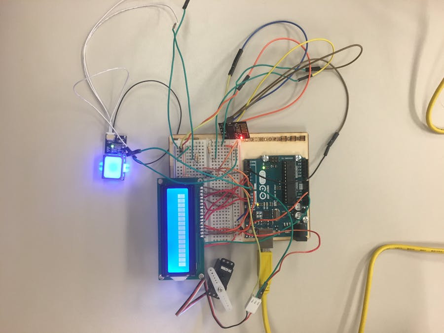
In this project, we built a fingerprint and web monitored garage door opener. Using an Arduino Uno as our microcontroller, we designed the system with the capability of mounting a finger print scanner on a house which, upon placement of an authorized finger, will cause the garage door to open and/or close. In addition, we implemented into the system an ESP8266 Wi-Fi Module which communicates with a web server to include the functionality of informing the owner of the current state of the garage door. In operation, the system is powered by a 9V battery. In order to authorize a fingerprint, the scanner has to run a built in enrollment process. After sending the fingerprint scanner a command to enroll, the finger must be pressed and released from the reader 3 times. This process is instructed via the LCD Module in the system. Upon completion of this enrollment process, the fingerprint is stored inside the scanning module’s memory. The fingerprint scanner used in this project has an increased memory capacity from older models and can store up to 200 different fingerprints. When an authorized user presses their finger onto the scanner, the LCD module reads either “Verified ID:” or “Unverified ID”. If the finger has been authorized, the state of the garage door will switch. Due to time and resource constraints, we did not actually wire the system into a garage door. Instead, we represent the state of the garage door by a servo which turns to one of two positions, representing the garage door being either “open” or “closed”.
The first step in this project was determining the basic hardware schematic and the components required. It was determined that a 9V battery would suffice for the power supply because the Arduino can be powered from 7-12V on the DC port. After some research, we decided to use the TTL-GT-511C3 fingerprint scanner. While there are other usable fingerprint scanners on the market, this specific scanner has the benefit of internally storing up to 200 fingerprints and there is a small support network online for this device if necessary. In order to boost the user-friendliness of the system, a simple 16X2 LCD was chosen to output commands and responses to the user.
While the fingerprint scanner and Wi-Fi module are both powered by 5V, they both communicate via 3V. To accomplish this, a voltage divider was implemented with a 560ohm resistor on the 5V side and a 1kohm resistor on the ground side. This voltage divider is placed on the TX line from the Arduino and the RX line of the Fingerprint Scanner comes from the 3.3V node.
The next step in the project was writing the software. To write the software, we first came up with a basic operation that the system needed to complete. The software should initially start in “Authorization” mode unless the pushbutton is pressed. If the pushbutton is pressed, the software will enter “Enroll” mode. The Enroll mode utilizes a function included in the FPS library written for the fingerprint scanner. This enroll function requires a finger to be pressed onto the reader 3 times, after 3 successful readings the fingerprint will be saved. After a successful enrollment, the software should start back in “Authorization” mode. In authorization mode, the scanner should wait for a finger to be pressed onto the scanner. Once a finger has been applied, the scanner should check if the print has been enrolled or not. If the print has been enrolled, the LCD should print as such and the state of the garage door should change. The displayed garage state in the web server should also change at this point. If the print has not been enrolled, the LCD should print as such and return to “Authorization” mode.
Fingerprint Authorization: Our fingerprint authorization feature works as we had originally planned. Our system features an enrollment process where the user may follow instructions on the LCD screen to authorize their finger print. This enrollment process is activated by depressing a pushbutton. When an authorized finger print is pressed onto the reader, the LCD screen will display whether or not the user is “Verified” or “Unverified”.
Garage Door state change via Fingerprint: Our system properly changes the position of our servo when an authorized user applies their fingerprint. The position of the servo is what we have used to test the functionality of our system without wiring into an actual garage door system. When an authorized finger print is applied, the servo will move to the position opposite the current state. For instance, if the servo is already in the “closed” state, the garage door will open. If we were to wire into an actual garage door system, we would most likely use a MOSFET and wire into the existing garage door button to integrate the system.
Wi-Fi view ability of Garage Door state: We are capable of viewing the state of our garage door on a web server via Wi-Fi. This is useful if the garage door owner needs someone to go to their house that does not have authorized access to open the garage door. The owner of the house can check the web server to see if the garage door is currently open, therefore allowing an unauthorized user to enter their house anyways. Similarly, the owner could also use this webserver to check the state of their garage door in case they cannot remember if they closed it on their way out of the house.
Wireless opening and closing via Wi-Fi: We are not able to open and close the garage door wirelessly via Wi-Fi. This feature was not an original requirement to meet the complexity of our project, yet we kept it as a potential option to add an additional feature to our project. Once we had met the complexity requirement of the project by adding Wi-Fi viewing of the garage door state, we were too pressured for time to implement Wi-Fi control of the garage door state. We placed more importance in finishing other required areas of our project than completing this additional option.
Conclusions: Throughout the course of this project, we got to design and build a project of our own choice. We were able to explore the possibilities of what we have the ability to add to our system in order to meet the difficulty requirements of the project. In effect, we got some practice in evaluating what is possible and not possible in terms of cost, time, and microcontroller capabilities. In previous projects, we have had to design our program to meet a specific problem statement, whereas in this project we got to come up with our very own problem statement and explore the possibilities of fixing it. Using everything we have learned this semester, we incorporated a servo, a pushbutton, and an LCD screen into our project while exploring new realms with our fingerprint scanner and Wi-Fi module. Instead of simply writing a program, we used our knowledge in circuit analysis and explored all sorts of hardware and module options to create a system that we can apply to real life. Throughout the course of this project, we began learning about the TTL-GT-511C3 fingerprint scanner and the ESP8266 Wi-Fi module. Neither of us had ever experimented with implementing either of this things into our projects before. We still have a lot to learn about the Wi-Fi module and creating web servers, but this project allowed us to step into these waters and have more confidence to use them in the future. While using the fingerprint scanner in this project we realized that there are basically endless applications for such a piece of equipment, we feel confident that we could potentially use this same finger print scanner to achieve certain large-scale outcomes in the future. Throughout this process we also learned about having to make difficult choices in large projects. When we were having extreme trouble getting our devices to work with the MSP450F5529 we were met with the confliction of either not finishing the project at all, or finishing the project with modifications to our original requirements. This led us into joining our decision making skills so that we could finish the project in a way that still satisfied both of us.


_3u05Tpwasz.png?auto=compress%2Cformat&w=40&h=40&fit=fillmax&bg=fff&dpr=2)
Comments
Please log in or sign up to comment.