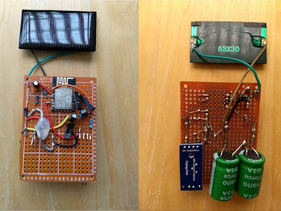
About a year ago, I built a moisture sensor for my garden. I had it connected to an ESP-12E chip, which sent me hourly updates on the moisture level via WiFi. To power it, I used three AAA batteries. While it was running great and the batteries lasted a long time because of the deep sleep feature of the chip (around 6 months), I wanted to build something that could keep running without my interference. The sensor was in a hard to reach place and because it was in a waterproof enclosure, it was a bit finicky to change the batteries. And apart from that I really liked the idea of building something that, in theory, could last for over a decade.
Finding the right power source for this was easy: the sun. The harder part was to store that energy. The ESP-12E is a power hungry chip. While starting a WIFI connection, it draws around 150-250 mAh. So powering the chip directly from solar panels was out of the question. To store the energy, I looked at different kinds of rechargeable batteries. There were a few drawbacks with using batteries though: a short lifespan, damaging them by over or undercharging them, etc. Then I came across an article by nick gammon on his excellent blog: https://www.gammon.com.au/forum/?id=12821
There, he describes using a supercapacitor to power his Arduino. That sounded like a great solution for my project!
When the supercapacitors arrived via mail, I thought everything would be very easy to build and would take me a day or so to get running. Now, two weeks later and after a lot of unforeseen problems solved, I finally have it working consistently. I'm a bit of a novice when it comes to electronics and I have certainly learned a lot during this process. The main reason I'm writing this down is so I can remember what I did to get this working!
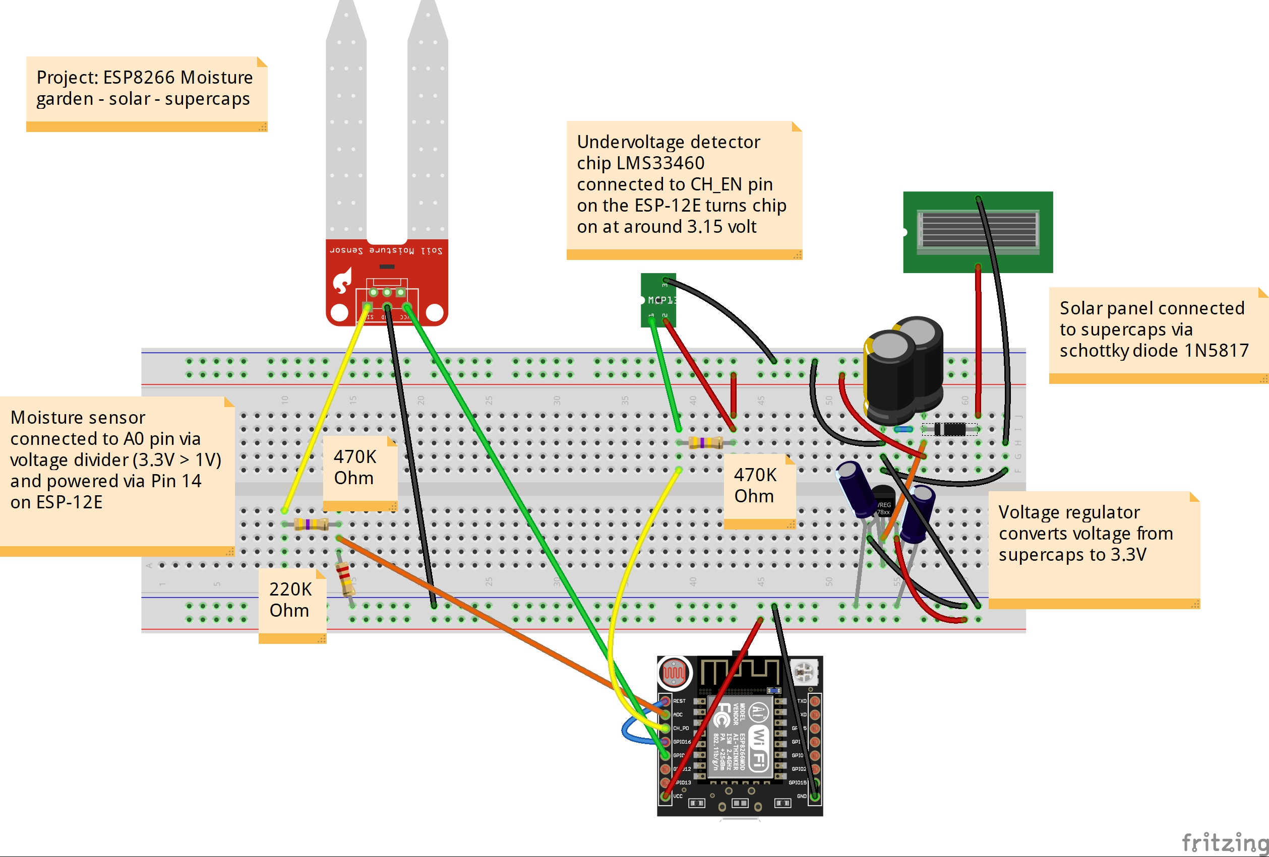
The Basic SetupThe 5V solar panel charges the two 22 Farad supercapacitors via a Schottky diode to prevent reverse current at night. The supercaps are placed in series to double the voltage (from 2.5V to 5V). The ESP-12E is powered via a HT7833 voltage regulator. The moisture sensor is connected to the analog pin via two voltage divider resistors to keep it under 1V. So far so good.
These parts are enough to get everything running. The problem is: this setup stops working when the voltage drops below a certain point. Below 2.7V the ESP-12E turns off. When after a while the solar panel charges the supercaps again, the chip turns itself on and draws so much power that the voltage immediately drops below the threshold and the chip turns off again. The chip is then stuck in this state. In other words, the system needs hysteresis.
A chip that adds this is the undervoltage detector LMS33460. Extremely tiny and difficult to solder but it's the only one I could find that fitted this design. It sends a HIGH signal to the CH_EN pin at around 3.10 volt and turns off when it drops below 3V. This is enough for the ESP8266 to run.
The SketchWhen the chip wakes up and executes the sketch it first connects to my network. It then downloads the last uploaded value from the Ubidots servers. Because the ESP8266 can't easily store values when it wakes up from deep sleep, that's the only way to compare values. It then takes a reading from the sensor and sends it to the internet services.
I use two services: Ubidots and Pushover. Every hour or so the latest value is uploaded to Ubidots.
I use Pushover to send me notifications about the moisture level. Receiving a notification every hour would become annoying quickly so I set it up to only send notifications when the new value is in a different category compared to the previous measurement (see code)
When it is done it goes to sleep for a little over an hour.


_3u05Tpwasz.png?auto=compress%2Cformat&w=40&h=40&fit=fillmax&bg=fff&dpr=2)


Comments
Please log in or sign up to comment.