


Hardware components | ||||||
 |
| × | 1 | |||
 |
| × | 1 | |||
| × | 1 | ||||
 |
| × | 1 | |||
 |
| × | 1 | |||
Software apps and online services | ||||||
| ||||||
An accelerometer such as ADXL-335 is connected to the ADC input of Arduino Nano to detect the vibrations from the sub-woofer (or any speaker for that matter). Arduino Nano does some processing on this input signal and generates a digital output. The digital output is then fed through suitable driver circuit to power some bright LEDs. A 9V battery is used to power the entire circuit. The complete assembly should be carefully placed inside a suitably sized plastic ball with the LED lights decorated along the outer circumference of the ball. Ensure that the accelerometer is placed firmly touching the inner bottom surface of the ball to get maximum sensitivity to the vibrations produced by the sub-woofer.
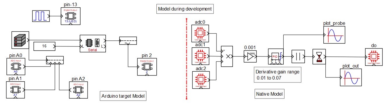
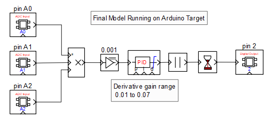
The three analog ADC input signals (X,Y,Z) from the accelerometer are multiplied and passed through a PID controller block where only derivative gain is used with rest set to zero. User can tune this gain value between 0.01 and 0.15 to get the desired sensitivity. The negative values of the output of the PID block is converted to positive by the absolute value block and the timer block is used as a drop off timer to retain the high output for some time.
The net effect is that when the sound level crosses the timer block pickup set level the LEDs turns ON immediately and turns OFF when the sound level goes below the timer drop off level but only after the set delay time.
ApproachThe required logic is developed with a model based software tool CASP. Initially, the three analog inputs signals are sampled by the Arduino board and each sample is transferred to the host PC via serial communication in real time. On the host PC, it is analyzed visually and suitable logic is developed and tuned to achieve the desired objective. The resultant digital output signal is transferred back to the Arduino board via the same serial link where it is extracted and used to drive a digital output pin that is controlling the LEDs.
Once the logic has being finalized and properly tuned, the same is then programmed to the Arduino board with the input and output GPIO blocks replaced with corresponding target hardware IO blocks of CASP..
1. Download and install CASP software https://aadhuniklabs.com/?page_id=550
2. Check these videos on how to install CASP https://aadhuniklabs.com/?page_id=554
3. Download files from Gitlab repository https://gitlab.com/tul.ishwa/projects/-/tree/main/music_lights and extract the zip file.
4. Build the circuit as shown in connection diagram
5. Run CASP. Open the project from the extracted zip file and open the workspace file wsp0.wsp.
6. Open Setup Simulation Parameters and set the hardware programmer port to the serial port where Arduino Nano is connected.
7. Build the model and program the board.
8. After the board is programmed place the assembly into a plastic ball of suitable size. Ensure that the accelerometer is placed firmly touching the bottom surface of the ball to get maximum sensitivity to the vibrations produced by the sub-woofer.
9. Place the ball on top of a sub-woofer and enjoy the music with lights.
10. Please note that model on the Arduino board will run only for finite time (may be 10 minutes or less based the license) as we are using free version of CASP. Just press reset button on the Arduino board to resume.
11. For any queries and suggestions please write to me at tul.ishwa@gmail.com


Comments
Please log in or sign up to comment.