


Hardware components | ||||||
| × | 1 | ||||
_ztBMuBhMHo.jpg?auto=compress%2Cformat&w=48&h=48&fit=fill&bg=ffffff) |
| × | 1 | |||
| × | 1 | ||||
 |
| × | 1 | |||
| × | 1 | ||||
| × | 1 | ||||
| × | 1 | ||||
| × | 1 | ||||
| × | 1 | ||||
| × | 1 | ||||
| × | 1 | ||||
| × | 1 | ||||
| × | 5 | ||||
| × | 2 | ||||
| × | 8 | ||||
| × | 8 | ||||
Software apps and online services | ||||||
 |
| |||||
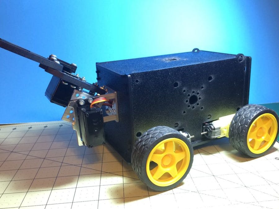
A few months back my son asked me to make him a remote controlled bot. He gave me a list of what he wanted and we narrowed it down to a manageable list :) This is what I ended up building for him...
- Take the UNO and V5 Sensor shield and snap them together.
- Place the joined UNO/Sensor board into the clip holder inside the center of the bot.
- Take Double sided tape and place the motor driver on the left inside wall and the bluetooth adaptor on the right wall.
For this project you could make your own chassis or choose another, the choice is yours.
Step 1: The Software NeededThings you will need to download:
- The Arduino IDE
- Python 2.7 (a full install with tkinter)
- The pySerial library
- The L9110S motor controller library attached .zip (See the files in this Step)
- The Robot code below or the attached .zip (See the files in this Step)
- The Python remote control application (See the files in this Step)
Parts you will need are as follows:
- Runt Rover Half-pint chassis or a suitable 4wd enclosed replacement
- Arduino Uno or similar board with USB cable
- V5 sensor shield
- L9110S motor driver (Get a couple as they are cheap)
- MG995 servo or another suitable replacement x2
- HC-05 or HC-06 bluetooth adaptor x1
- Standard servo plate B x1
- 90 degree bracket x1
- Single bracket x2
- Lightweight servo hub (525125 for Futaba) x1
- Standard Gripper Kit A x1
- Female to Female jumper wires
- 5 rechargeable AA batteries (NiMH) and charger
- Double sided sticky tape and small zip-ties
- A 'AA' 5 slot battery pack (if you go the AA rechargeable option)
- 6v NiMH or 7.4v Li-ion battery pack and charger
- 1.250" 6-32 screws x2
- .750" 8-32 nylon spacers x2
- .500" 6-32 screws with nuts x8
- .3125" 6-32 screws x8
You can source many of the parts from eBay or other suppliers directly like Sparkfun, Adafruit and ServoCity.
After you have purchased, collected and downloaded everything thing you're ready to start with the build.
Step 3: Assembly - The ChassisFirst assemble the chassis following the instructions included with the chassis or video. After finishing you should have something like the image. When you place the plate that holds the controller on the bot, make sure you place it in the middle holes. This will leave space in the front and the rear of the bot.
NOTE: Before going any further, please remove all 4 wheels, so as not to damage the motors whilst putting the other bot components on.
Step 4: Assembling the GripperAssemble gripper following the instructions provided in this video. After finishing you should have something like the image.
Step 5: Mounting the Gripper - Step 1Take the 90 degree bracket, lightweight servo hub and four (4) of the .3125" screws for this step:
Take the servo hub and place it on one side of the bracket and secure them together with the .2125" screws like pictured and set it aside Place the nuts on the two shorter screws and tighten them down Now tale the two Single brackets, the 1.250" screws and two .500" screws with nuts, 2 nylon spacers and the Servo plate B. Take one single bracket and place in in the inside of the Half-pint bot and run the 2 1.259" screws on on the left holes (from the inside) and the 2 .500" screws on the right side. All of the screws heads will be on the inside of the bot as pictured. now place the second single bracket on the screws on the outside of the bot. Next take the nylon spacers and place them on the longer (1.250") sticking out and then screw the servo plate onto the long screws Tighten down the screws going to the servo plate with a hex key of the proper size or screw driver if you used normal screws.
Use the pictures for reference as needed.
- Next take the remaining servo you have and place it in the servo bracket with the spine to the top. Secure it in with 4 of the .3125" screws.
- Next take the 90 degree bracket with the servo hub on it and mount the gripper on to it with the 4 of the .500" screws using 2 of the 8-32 nuts as spacers between the bracket and the gripper as pictured. Secure with another nut on top of the gripper (on under the bracket if you turn the screws the other way)
- Now take the gripper assembly and place it onto the servo and use a servo screw (from your servo packet) to hold it in-place, firmly securing it.
After you are finished, run the two servo wires though the flat bracket hole to the inside of the bot.
See the pictures for more detail and reference.
- Take the UNO and V5 Sensor shield and snap them together.
- Place the joined UNO/Sensor board into the clip holder inside the center of the bot.
- Take Double sided tape and place the motor driver on the left inside wall and the bluetooth adaptor on the right wall.
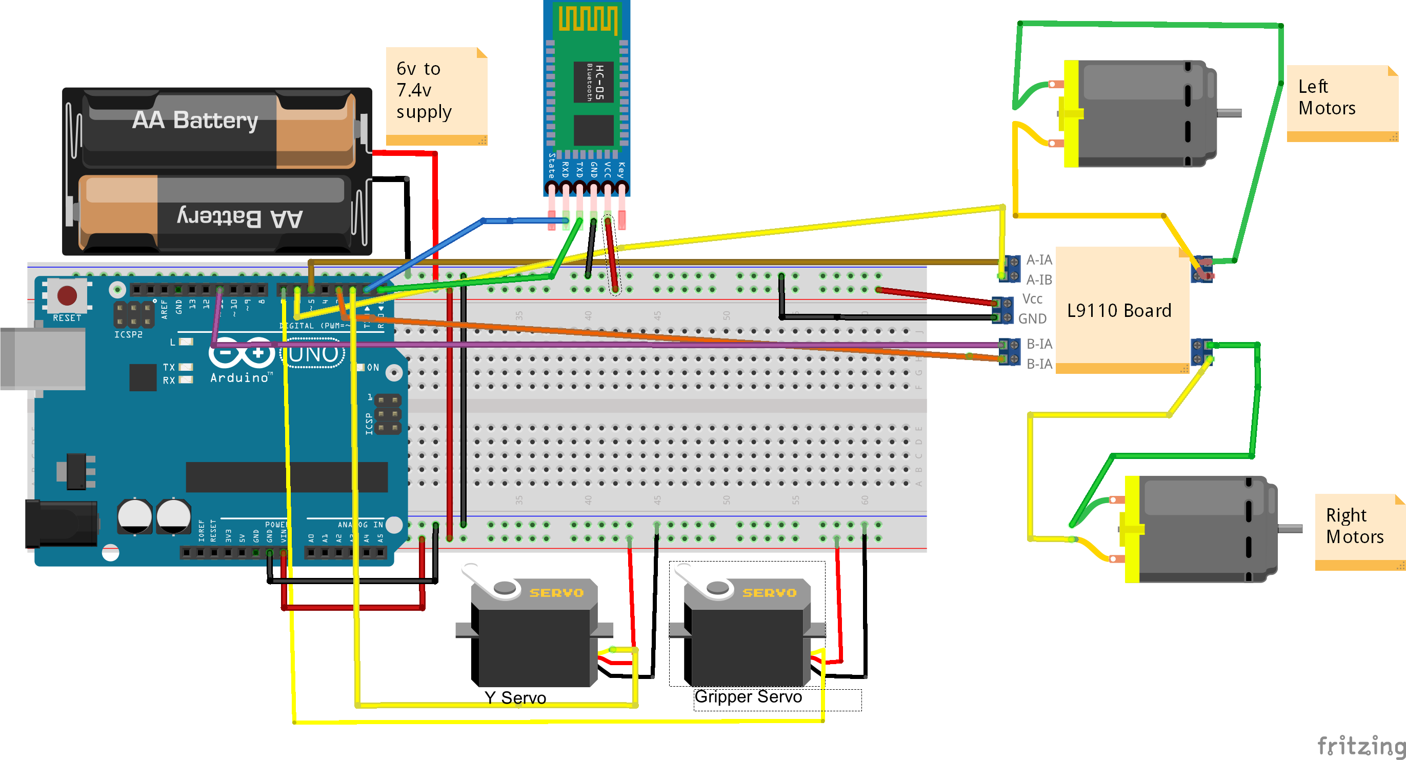
- A-1A pin on the motor driver to pin 5 on the sensor shield
- A-1B pin on the motor driver to pin 6 on the sensor shield
- B-1A pin on the motor driver to pin 3 on the sensor shield
- B-1B pin on the motor driver to pin 11 on the sensor shield
Now with the robots front facing AWAY from you, take the wires on the LEFT side and -
- Connect the two BLACK wires on the left to the first output screw terminal for Motor A
- Connect the two RED wires on the left to the second output screw terminal for Motor A
Take the wires on the RIGHT side and -
- Connect the two BLACK wires on the left to the first output screw terminal for Motor B
- Connect the two RED wires on the left to the second output screw terminal for Motor B
The Servos:
- Now connect the Y servo wire to pin line 2 on the sensor shield. The white or orange wire is always the signal wire.
- Now connect the X (Gripper) servo wire to pin line 7 on the sensor shield. The white or orange wire is always the signal wire.
- Bluetooth adaptor Tx -> sensor shield pin 0
- Bluetooth adaptor Rx -> sensor shield pin 1
Connect the power leads from the 5 'aa' (or other 6v pack) battery pack to the sensor shield's power screw terminal:
- Red to Vcc
- Black to GND
- Next make sure the jumper on the V5 sensor shield is in place on the jumper pins.
- Connect the GND pin on the L9110s driver to a GND pin on the sensor shield.
- Connect the Positive wire from the 6v or 7.2v battery or other battery you have chosen for the motors to the Vcc pin on the L9110S motor driver.
- Connect the Negative (GND) wire from the motor battery a GND pin on the motor shield.
Now you will need to go into the bluetooth device settings on your PC from the OS's "Control" or "Systems" Panel or use Google to help.
Possible OS Bluetooth setup information:
You will need to note the serial port device name or number that is assigned to it.
Step 12: Loading the CodeWith the wiring checked and rechecked, It's time to load the code. Follow the instructions on the Arduino site on how to install the Arduino IDE.
After the IDE is installed, you can next install the L9110 Motor Driver library. Do this by downloading the zip file included in STEP 1 named L9110Driver.zip and extracting it to your Arduino libraries folder or by following these instructions on how to add a library.
Now that the IDE and Motor driver library have been installed, load the robot code into the Arduino IDE from the zip file found in STEP 1 named blue_t_slave.zip. These files are also included in this step as well.
Connect your PC and Arduino up with the USB cable. Now choose the board from the Tools->Board menu in the IDE, Uno for this project (choose the board you have if different from Uno) Now from Tools->Port menu, pick your com port. After this is done, click the upload button. If all went well, the code was loaded, if not see here for help on the IDE and related issues.
Step 13: Running the Python Control ApplicationTo run the Python remote control application, download the zip file from this step and extract it to the location you want to run it from. Next, open a command shell (i.e. terminal, cmd.exe, etc...) and navigate to the directory you extracted the file to. Now type: python rover.py from the command line and a window looking like the one in the image should pop up. If not, look for any python errors and correct (i.e. missing libraries etc...) The Python site may help some if needed.
Once the App is running, you should be ready go.
Now, power on the bot. Then type the comm port of your adaptor and click the "Connect" button. After a few seconds you should see the other controls enabled and the connect button disabled. This means you are connected to the robot. If you can't connect to the bluetooth adaptor, you will have to use the magic of Google to help you out!
The control application is simple to use and allows for mouse or keyboard controls.
The keyboard controls are:
- Arrows are forward, reverse, turn left 90 degrees, turn right 90 degrees
- a - turn left 45 degrees
- s - turn right 45 degrees
- h - halt (stop)
- y - set Gripper Y axis
- u - set gripper open/close
- c - gripper home
Forward and Reverse commands are constant i.e. they keep the bot moving after execution until a new direction is sent or a Halt command.
The turns 90 and 45 degrees are temporary i.e. After some delay, they stop the bot from moving.
The gripper sliders do not automatically set the gripper on the bot. You have to hit the corresponding "Set" button or key to do the actual execution of the set.
The Slider values range from 0-180.
- Gripper Y Axis: 0 is All the way up and 180 is all the way down.
- Gripper Open/Close: 0 is all the way closed and 180 and all the way open.
Use the "Disconnect" button to stop using the program. This will send commands to stop the bot and home the gripper.


Comments
Please log in or sign up to comment.