Building and playing with robots is my main guilty pleasure in life. Others play golf or ski, but I build robots (since I can't play golf or ski :-). I find it relaxing and fun! To make most of my bots, I use chassis kits. Using kits helps me do what I like doing more, the software and electronics and also makes for a better chassis for my all-thumbs self.
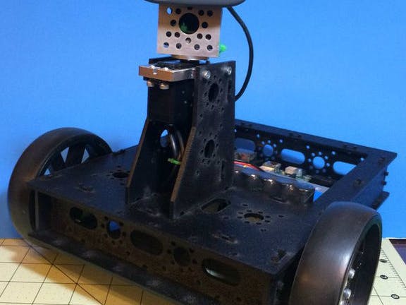
In this Instructable, we will look in what it takes to make a simple but robust Wifi/web controlled rover. The chassis used is the Actobotics Gooseneck. I chose it for it's size, expand-ability and cost but you can use any other chassis of your own choosing.
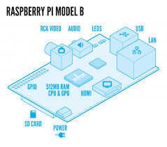
For a project like this, we will need a good solid single board computer and for this bot I chose to use the Raspberry Pi (RPI) a Linux based computer. The RPI (and Linux) gives us lots of coding options and Python will be used for the coding side. For the web interface I use Flask, a lightweight web framework for Python.
To drive the motors, I chose a RoboClaw 2x5a. It allows for simple serial communication for commanding it and works well with the RPI and the motors on the Gooseneck.
Finally, it has a webcam for POV type video feedback for driving it remotely. I will cover each topic in more detail later.
Step 1: Hardware needed
- Actobotics Gooesneck chassis or a suitable replacement of your choice
- Raspberry Pi of your choice (or clone) - An RPI model B is used on this bot, but any with at least two USB ports will work
- Standard Servo Plate B x1
- 90° Single Angle Channel Bracket x1
- RoboClaw 2x5a motor driver
- Small breadboard or Mini breadboard
- Female to Female jumper wires
- Male to Female jumper wires
- Web cam (optional) - I use a Logitech C110, and here is a list of supported cams for the RPI
- 5v-6v power source for servo power
- 7.2v-11.1v battery for drive motor powering
- 5v 2600mah (or higher) USB power bank for the RPI
On my bot, I use 4" wheels to make it a little more All-Terrain-Indoor. For this option you will need:
Step 2: Assembling the chassis
First assemble the chassis following the instructions included with the chassis or video. After finishing you should have something like the image. NOTE: When assembling the Neck part, just leave the mounting bracket off.
On my bot, I chose to replace the wheels that the chassis came with for 4" heavy duty wheels. This is optional and not needed unless you want to do the same.
Step 3: Mounting the electronics
The Gooseneck has a lot of room and options for mounting your electronics. I give you these pictures as a guide line, but you can choose how you would like to lay it all out. You can use stand-offs, double-sided tape, Velcro or servo-tape to mount the board and batteries.
Step 4: Adding the Webcam
Take the 90 degree bracket, lightweight servo hub and four (4) of the .3125" screws for this step:
- Take the servo hub and place it on one side of the bracket and secure them together with the .2125" screws like pictured
- Next mount the servo into the servo bracket
- Attach the 90 degree bracket with the servo horn to the servos spine and use the horn screw that came with the servo to connect them together
- Now mount the Servo in bracket onto the top of the goose-neck with the remaining screws
- Mount camera with zip-ties or double sided tape on to the 90 degree bracket
Use the pictures for guides if needed.
Step 5: Wiring it all up
The wiring is fairly strait forward for this robot.
The Motors:
- Solder leads on both motors if you have not done so already
With the robots front (the end with the goose-neck) facing away from you:
- Connect the motor wires on the left motor to the channel M1A and M1B
- Connect the motor wires on the right motor to the channel M2A and M2B
Ground (GND) connections:
- Connect one ground pin on the RoboClaw to the ground jumper board. The ground pin line on the RoboClaw is closest to the center (See pic)
- Connect PIN 6 on the RPI to the jumper board. See the RPI header pic for pin assignments.
- Connect the GND from the servo battery pack to one of the pins on the jumper board.
- Run a jumper wire from the jumper board to the servos GND wire.
RPI to RoboClaw:
- Connect the RPI GPIO14 TXD pin to RoboClaw S1 pin
Power:
- Connect the POS wire from the servo battery to the servos POS lead
- Connect the POS wire from the motor battery to POS (+) of the RoboClaw motor power input terminal. We will leave the GND terminal disconnected for now.
Step 6: Setting up the RPI
I assume the user here knows some about Linux and the RPI. I do not cover how to setup or connect to one. If you need help with that then use the pages below.
To get your RPI setup, have a look at the following pages:
For general jump-off pages, The RPI main page and the eLinux pages are great places to start.
If you plan on using some sort of camera or web cam on the bot, have a look at these pages to get the basic needed files.
Streaming video:
There are a few ways to get video streaming working on a RPI, but the method I prefer is using Motion.
To install it on your RPI run this: sudo apt-get install motion
This instrucatable goes over setting it up for streaming as well.
Step 7: Configuring the RPI serial port
We will need to disable the Linux console mode for using the RX and TX as we want to talk to the RoboClaw motor controller from this port. To do this, you can use this method or this tool. The choice is yours on the method as they both do the same thing in the end.
Step 8: Installing the Python modules
You will need python installed on the RPI as well as the python package installer pip.
To install pip do:
- sudo apt-get install python-setuptools
- sudo easy_install pip
Then:
- sudo pip install flask
- sudo pip install pyserial
- sudo pip install RPIO
This will be all the modules needed for the code to run.
Step 9: Setting up the RoboClaw
I have the robot code talking to the RoboClaw in Standard Serial Mode at 19200 baud.
To set the RoboClaw up for this do:
- Hit the "MODE" button on the RoboClaw
- Hit the set button until the LED flashes 5 (five) times between the delays
- Hit the "LIPO" button to store
- Next hit the "SET" button until the LED flashes 3 (three) times between the delays
- Hit the LIPO button to store
That's it for setting up the motor controller. See the pdf linked above for more info if needed.
Step 10: Installing the rover program/files
Download and copy the rover.zip file to your RPI in your pi user directory.
If you are running Linux or a Mac, you can use 'scp' to do it:
scp ~/location/of/the/file/rover.zip pi@your_rpi_ip:/~
For Windows, you can download and use pscp and then do:
pscp /location/of/the/file/rover.zip pi@your_rpi_ip:/~
Once the zipfile is copied over to the RPI, log into it as the pi user.
Now run:
unzip rover.zip
This will unzip the files to a folder named 'rover' and have the following under that folder:
- restrover.py (The python code for the robot)
- static (holds the image files for the buttons on the control page)
- templates (holds the index.htlm file, the control web page)
If you are using a web cam, modify line near the bottom of the index.html file in the template folder. Change the URL in the IFRAME line to match the src URL for your video stream.
Step 11: Starting the bot up
Connect the USB power to the RPI.
To start the bot code up, log in as the pi user and run:
- cd rover
- sudo python restrover.py
If all was OK, you should see a screen similar to the image in this step
If you see any errors or issues, you will have to fix them before going forward.
Now, connect the the GND (-) wire to the NEG (-) terminal on the RoboClaw motor power input.
Step 12: Accessing the bot control page
After the robot's python script is running, power up the RoboClaw and then navigate to your RPI's ip like:
You should see the Web control page pop up like in the images. If not, check your RPI output terminal and look for any errors and correct them.
Once on the page, you are ready to control the bot.
The robot will start in the "Med run" setting and at the Medium speed.
The bot can be controlled via the buttons on the page or by keys on the keyboard.
The keys are:
- w - forward
- z - reverse/backward
- a - long left turn
- s - long right turn
- q - short left turn
- e - short right turn
- 1 - pan camera left
- 2 - pan camera right
- 3 - pan full left
- 4 - pan full right
- / - home/center camera
- h - halt/stop robot
There is an half second delay buffer between commands sent. I did this to eliminate unwanted repeated commands. You can of course remove this from the code if you like (in index.html)
The rest of the controls and controlling it should be self explanatory.
Step 13: The Python/Flask code
This bot uses Python and the Flask web framework. You can learn more about Flask here if you are interested.
The big difference from a Flask app and normal Python script is @app.route class/method used to do the URI handling. Other than that it's pretty much normal Python for the most part.
Code Below.
Step 14: Using other hardware
If you want to use other hardware, like another type of SBC (Single Board Computer) you should have little issues getting Python and Flask running on other boards like the Beagle Bone, PCDuino etc... You will have to change the code to match the GPIO layout and use the servo driving capabilities of the new board.
To use another type motor driver, you just need to modify the go_forward, go_backward, go_left, go_right and halt functions to do what ever the replacement motor driver needs to make the motor do that particular function.


Comments
Please log in or sign up to comment.