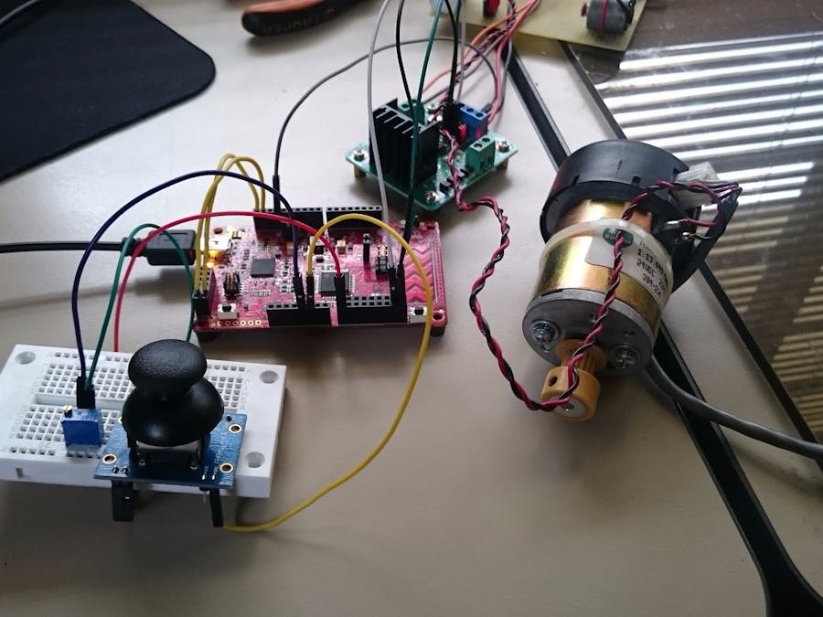
When it comes to controlling brushed DC motors the drive system is the H Bridge one of the most used in demo boards is the L298N IC H bridge.
So here we have a schematic wiring and functional diagram of how it is commanded.
To select the rotation direction we will use a control register (this is a software or firmware controlled hardware digital output block this works way faster than writing values directly on pins).
Then on the code I named the two possible outputs we will use when the value written is 0x01 In1 =1 and In2=0, when the value is 0x02 In1=0 and In2=1.
#define CCW()ControlReg_Write(0x01);
#define CW() ControlReg_Write(0x02);
Now the speed command will be routed to the Enable A pin 5V = full speed, 0=stop and PWM= variable speed (this value doesn't change with the rotation of the motor).
The period is 255 and the initial compare value is 0. Now this part requires some external wiring to a potentiometer.
Since the maximum voltage the PSoC can convert with the ADC is 3.3V we must create a voltage divider so that the joystick gets the 3.3V, this way when the Joystick is centered the voltage will be 1.65V and on the limits 0 and 3.3V.
You can verify this values with a multimeter.
The ADC config is shown below:
We are only working with one channel with 256 averaged samples.
Right after the End of conversion interrupt and ADC conversion are started for a more accurate calibration I used the joystickzero variable this way it doesn't matter that the actual voltage on the Joystick is not 3.3V we know which is the center position and that will be the reference command.
ISRADCEOConv_StartEx(ADCEOC);
ADC_Start();
ADC_StartConvert();
CyDelay(50);
joystickzero=mVoltsA;
The end of conversion Interrupt sequence is detailed below.
#define CHA  (0u)
CY_ISR(ADCEOC){
   adcCountsA = ADC_GetResult16(CHA);
   mVoltsA = ADC_CountsTo_Volts(CHA,adcCountsA);
   dutyc=(mVoltsA-joystickzero)/joystickzero*PWMmaxcomp;
   mot=dutyc;
   motoroutput();
}
SAR ADC stands for Sequencing Successive Approximation Register Analog to Digital Converter.
A very simple way of explaining how this works is with the counts.
if the ADC is working with a resolution of 12bits that means that it has 4096 different voltage counts so if 4096 counts are equivalent to the 3.3V then each count is equivalent to 0.8mV.
The SAR ADC compares the analog voltage to a number of counts and then returns the equivalent number of counts.
Now for the Motor Speed and rotation output we use this function and the CW and CCW definitions.
#define PWMmaxcomp 254 //Period 255
void motoroutput(){
    if((mot>=0)&&(mot<PWMmaxcomp)){
        PWMSpd_WriteCompare(mot);
        CCW();
    }
    else if ((mot<0)&&(mot>-PWMmaxcomp)){
	PWMSpd_WriteCompare(-mot);
        CW();
    }
}
Notice the maximum compare value has to be smaller than the Period on the PWM so it is defined as 254.
what this function does is simply separate the sign of the command variable and output the appropriate PWM value and rotation values.


_3u05Tpwasz.png?auto=compress%2Cformat&w=40&h=40&fit=fillmax&bg=fff&dpr=2)
Comments
Please log in or sign up to comment.