


Hardware components | ||||||
 |
| × | 1 | |||
 |
| × | 1 | |||
Software apps and online services | ||||||
 |
| |||||
If you search on the web for ball and beam control, you will find lots of projects. All of them are approached differently; there is so many ways to make this work.
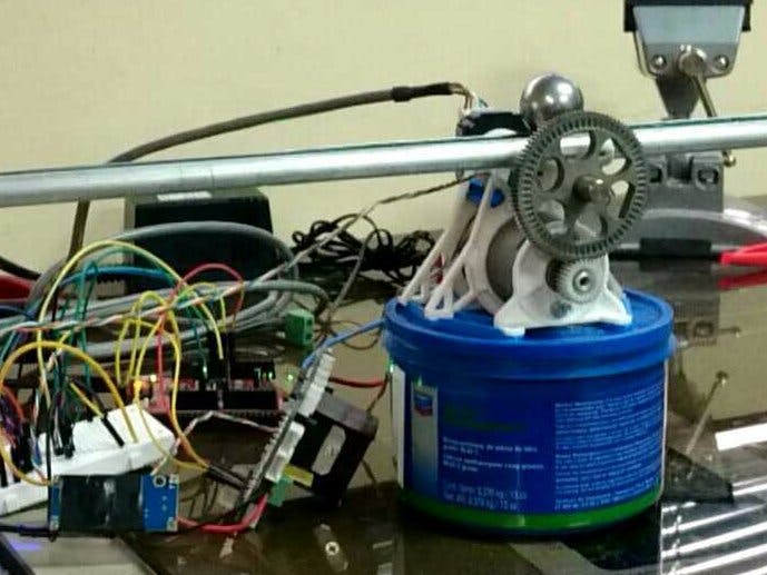
My approach is a tilting beam with a centered actuator on the rotational axis. Since I didn't have a motor with a gearbox, I had it built myself with some salvaged gears from an old inkjet printer and 3D-printed parts.
The first designThe first design considered a two gear reduction (3.46 ratio); this didn't provide enough torque to hold the ball on top of the beam, so I added a third gear.
This modification allowed for two possible gear ratios with two different third gears. So I had two alternative ratios (7.54 and 11.54).
Thanks to the power of PSoC, the electronic circuits are reduced significantly. Here I included an schematic for the whole system.
The position sensor is basically a large potentiometer consisting of two wires, the one is conductive and the other is resistive (Nichrome). When the ball is placed over the beam, it shorts both wires in the current position if one is grounded and the other is wired to a positive voltage (1.024V). In this case, depending on the ball position, we will get a different wire resistance, hence a variable voltage. Here is the schematic including a low Pass filter. The output voltage is wired to the other side of the resistive wire.
As you can see, the system has a very simple circuit; it is just messy because of all the wiring.
The PosSens pin is wired to an OpAMP and the ADC converter inside the PSoC, so these two go one next to the other. On the EoC pin on the ADC block, I am triggering an interrupt for data processing purposes.
The beam angular position is measured with the encoder. The encoder reading is very simple with the Quadrature Decoder UDB block. I wired each encoder channel to an LED for easy troubleshooting encoder wiring problems.
To fully control a DC motor with reversing direction and variable speed, we need a PWM and a control register to select the polarity or rotation.
Finally, these two blocks: UART for communication with the PC and a Timer to include a time stamp on data sent to the PC for monitoring or data processing.
If the system was made with a different controller the electronics or the programming would've been a whole lot more complicated.
NOW lets get to the EASY part - sensor reading.
For the QuadDec block, we will configure:- counter size 32 bit
- counter resolution x4
- we must clear the "use index input" checkbox and the "enable glitch filter" checkbox
To read the count number just use this:
counter=QuadDec_GetCounter();
And to convert it to the actual beam angle (in my case the encoder counts 1000ppr):
ang=counter*360/1000/4;//deg
On the init function:
QuadDec_SetCounter(0);
QuadDec_Start();
The OPamp was configured like this:
Then the ADC SAR Seq. is running at a 7000kHz freq, the Vref is 1.024V, averages 256 samples.
Then the acquisition time is 2 clocks, and we are sequencing only one channel on single mode and averaging at A clocks with limit detect.
On the code side, I defined the Channel number for easier reference and defined the End of Conversion routine for the interrupt. The commented formula on the code was the result of a linear regression of different data points that were measured with ball position with it. I have a linear relation between voltage and position in millimeters. Then the Interrupt start routine (this one is called on the init function).
#define CH0 (0u)
CY_ISR(ADCEOC){
 //y = -0.6423x + 404.66R² = 0.9944
 adcCounts = ADC_GetResult16(CH0);
 meas= ADC_CountsTo_uVolts(CH0,adcCounts);
 X=-0.6423*meas/1000+322.6;
}
//INIT
ADC_Start();
ADC_StartConvert();
opamp_Start();
ISRADCEOC_StartEx(ADCEOC);
This sensor data can be verified and plotted with either micrium uProbe or a program such as Matlab or Python.
With the help of Micrium uProbe (and some codes from the motor position control), I made these plots to show that the sensor measurements are okay.
You may notice that both plots have the same shape. What I did was make the Motor follow a set point equal to the ball position/100 radian (green line). (You will understand how I made this on the next part of the project.)


_3u05Tpwasz.png?auto=compress%2Cformat&w=40&h=40&fit=fillmax&bg=fff&dpr=2)
Comments
Please log in or sign up to comment.