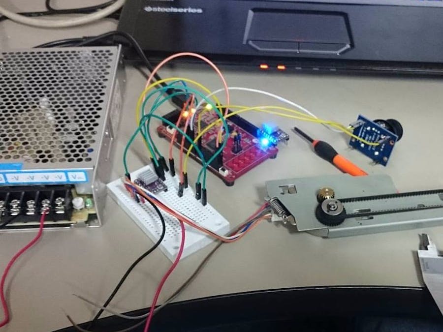
Stepper motors are very widely used on machines from traditional printers to 3D printers, and even manufacturing machinery with CNC controls; these being lathes, mills, cutters, etc.
Because they are both simple and accurate, their implementation for machine design is very straight forward.
In this project, I will be using two stepper motors with drives DRV8825 and draw on a Etch a Sketch. Line interpolation is achieved with relative speeds on the X- and Y-axis.
To control the driver, we need at least 3 pins: STEP, DIRECTION, and SLEEP. For more accurate control, we could work with M0, M1, and M2 to change the step resolution.
This page describes very well how the driver works: (DRV8825).
FunctionsThe direction signal is very simple: 0 or 1 will change the rotation of the motor from CW to CCW.
Sleep Pin will shut off any current sent to the motor COILS (this way the motor won't heat up when stopped).
For the Step pin we need a variable period signal, this way we can control the frequency of the command pulses or the motor rotational speed.
A smaller period will mean a faster signal (more pulses per second), and a larger period will mean a slower signal. The duty cycle can be 30% for this square wave.
How can we make a variable period signal with a fixed clock PWM block on PSoC?
The PSoC PWM blocks (UDB and TCPWM) work with counts. Each count is measured in one clock pulse, so depending on the number of counts, the period is set so we can configure the PWM signal period. For each new period we need a proportional compare value to keep the signal shape proportional (in this case, always 30% duty cycle).
So each motor will get an independent PWM Signal; notice they are both working with a fixed clock.
AccuracyNow the accuracy of the motor motion depends on how many steps the driver received, and at the same time the number of steps are very likely to be different. We should know each motor count before stopping each motor.
In this case, the X-axis needs to make 10 steps and the Y-axis 5 steps. Since we can control the motor speed, we can make the Y-axis run at half the speed as the X-axis and then only verify the number of steps made by either one of the motors. I would rather get the number of steps of the 10 steps motion in this case.
Implement on PSoCHow this can be implemented on PSoC.
With a Multiplexer, we can select the Motor Steps command signal we want to read with a control register. Then with a Counter Block, we can configure the number of steps the motor has to take before triggering the interrupt that stops the signal, and triggers the sleep mode if necessary.
For the direction and sleep pins, it would be best to use control registers, but for this chip the resources are kind of limited. I had to use the Enable pins as software controlled pins (slower than control register).
And finally, to use a trigger input, I used a debouncer to connect to a switch and an interrupt.
The code is fairly simple; this is the stop motors routine:
void Stop(){
   PWMX_Stop();    PWMY_Stop();
   disableX()      disableY();
   a=0;//b=0;
}
Counter interrupt routine:
CY_ISR(CounterISR){//counter iSR
   Stop();
   Counter_STATUS;
   Counter_ReadStatusRegister();
   CountINT_ClearPending();
}
Motor command and configuration routine:
void command(){
   Stop();dirx=1;diry=1;a=1;b=1;//DIR Y inverted
   if(dx<0){dirx=0;dx=-dx;}// dirx=dx > 0?1:-1;
   xdir_Write(dirx);
   if(dy<0){diry=0;dy=-dy;}//diry=dy > 0?1:-1;
   ydir_Write(diry);
  if(dx>=dy){
       speedy=nspeed*dx/dy;
       if(dy==0)speedy=nspeed; //slower
       speedx=nspeed;
       steps=dx;
       Sel_Write(0);
   }else{//dy>>
       speedx=nspeed*dy/dx;//slower
       if(dx==0)speedx=nspeed;
       speedy=nspeed;
       steps=dy;
       Sel_Write(1);
   }
   Counter_WritePeriod(steps+3);
   Counter_WriteCompare(steps);
   PWMX_Start();PWMY_Start();
   PWMX_WritePeriod(speedx);
   PWMX_WriteCompare(speedx/3);
   PWMX_WriteCounter(0);
   PWMY_WritePeriod(speedy);
   PWMY_WriteCompare(speedy/3);
   PWMY_WriteCounter(0);
   Counter_WriteCounter(0);
   if(dx!=0){enableX();}//LEDA_Write(0);
   if(dy!=0){enableY();}  //LEDB_Write(0);
}


_3u05Tpwasz.png?auto=compress%2Cformat&w=40&h=40&fit=fillmax&bg=fff&dpr=2)
Comments
Please log in or sign up to comment.