


Hardware components | ||||||
 |
| × | 1 | |||
The Analog Discovery is a tool most commonly used in Analog Circuits Classes. Used for its Oscilloscope, Waveform Generator, Network Analyzer, and Power Supplies, all great features.
However, many students go through those analog classes wondering, what are all of the wires to the right of the analog stuff. If you did do that, not to worry, I felt the same way.
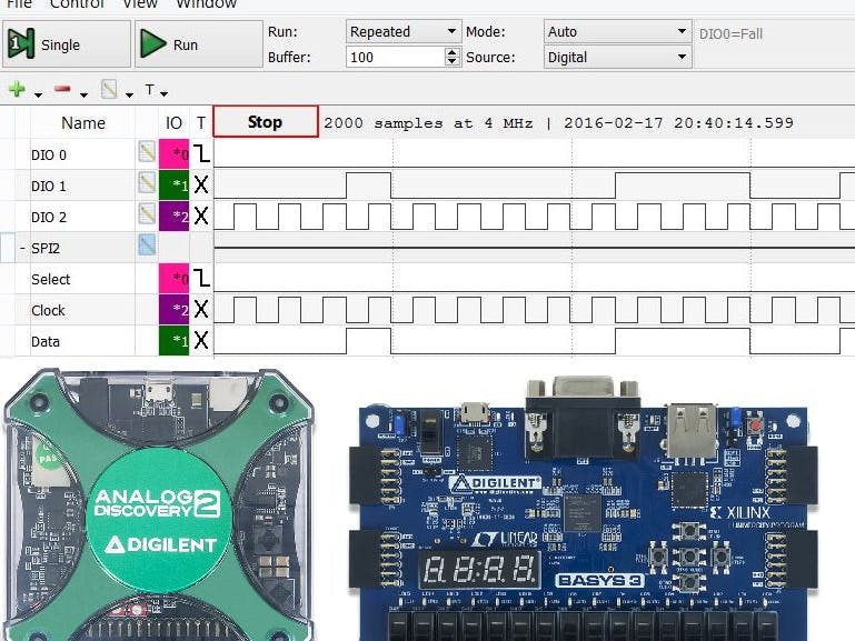
It wasn't until my second digital logic class that I was introduced to the Logic Analyzer on the Analog Discovery. It allows you to view digital signals in real time, and interpret them.
In this tutorial I go through how to use the logic analyzer with a SPI demo on the Basys 3 as an example.
To read more about my experience read this blog post.
Step 1: Gather MaterialsWhat You'll Need:
- 1 Basys 3 or Nexys 4 DDR
- 1 PmodAMP2
- 1 PmodMIC3
- Waveforms 2015 or Waveforms Classic Installed
- Xilinx Vivado Installed and Licensed. If you have another output you'd like to scope on another project you can use that. However, I will be giving you an example project to work with. You need Xilinx Vivado to run this example project.
- Headphones
Open Waveforms 2015. You should see this window if the Analog Discovery is not plugged into your computer.
Step 3: Plug in Your Analog Discovery 2Plug in your Analog Discovery using one of the USB A to USB Micro B Cables. You should see the Analog Discovery appear in the devices list as shown in the image in this step.
Step 4: Open the Logic AnalyzerOn the left panel click the button that says logic to open the Logic Analyzer. It should be the 5th button down.
Step 5: Add a Digital I/O SignalClick the green plus to add a signal. First I'll show you how to add a general Digital I/O signal. Click on signal to add a Digital I/O signal.
Step 6: Repeat Two More TimesRepeat two more times for a total of 3 Digital I/O signals.
Step 7: Add a SPI ChannelNow add a SPI Channel
Click the same green plus, but this time instead of clicking signal, click SPI.
Step 8: Change the Settings To Match the Test DesignChange the settings on the SPI channel. The settings above match the SPI demo that I will be using. These settings are important to make sure that the SPI data is interpreted correctly.
Step 9: Open the Test Project and Program Your BoardDownload, Extract and Open the SPI Project in this step.
Generate the bit file and program the Basys 3.
Step 10: Plug Three 6 Pin Headers into a BreadboardTake three 6 pin headers and plug them into your breadboard as shown.
Step 11: Plug One Pmod Cable Into the BreadboardPlug one Pmod cable into the breadboard as shown. Pay close attention to the placement of the star.
Step 12: Plug the Other End Into the PmodMIC3Plug the other end of that Pmod cable into the PmodMIC3, paying close attention to the location of the star.
Step 13: Plug the Second Pmod Cable Into the BreadboardPlug the second Pmod cable into the breadboard making sure the star is in the same location as the first Pmod cable.
Step 14: Plug The Other End Into the Basys 3Plug the other end of the Pmod cable into the Basys 3 paying close attention to the location of the star. If it was on pin one of the PmodMIC3 it needs to be on Pin 1 of the Basys 3.
The PmodMIC 3 will be our master and the Basys 3 will be our slave.
Step 15: Plug Three of The Digital I/O Wires into on the 6 Pin HeadersTake Digital I/O wires 0, 1 and 2 and plug them into the last Pmod header as shown. These will scope Data, CS, and SCLK.
Step 16: Your Entire Set Up Should Look Like ThisOnce put together, this is what your set up should look like.
Step 17: Change the Chip Select to Falling Edge TriggeredRight click on the X by the CS signal and change it to Falling Edge triggered.
Step 18: View Your Logic SignalsNow you can press run, or single and view your logic signals. Run will show the signals in real time, and single will take a snapshot of the signals.
Notice as you talk you can see the value that the SPI channels shows changing.
If you plug the PmodAMP2 into the top of Pmod port A, and plug in your headphones, you can hear the output as well.
To read more about my experience read this blog post.


Comments
Please log in or sign up to comment.