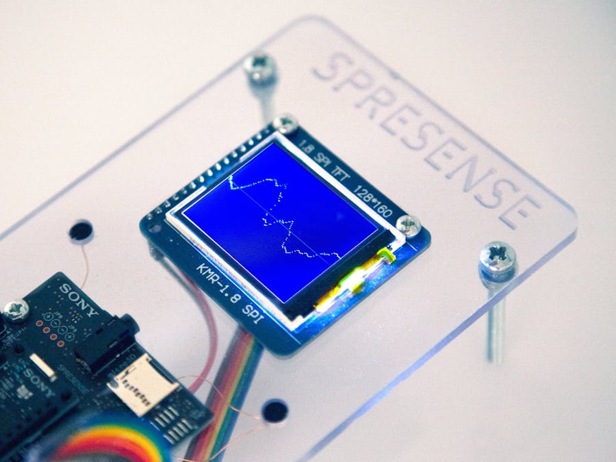
This project uses the Spresense board and its audio capabilities to record an audio signal. It has an electret microphone connected to one of the microphone inputs on the Spresense board. The analog signal from the microphone will be converted to a digital data stream and then plotted on the TFT display.
DetailsThe Microphone
The Spresense audio driver is by default configured to support analog microphones. The electret microphone used in this project needs a small biasing voltage on the signal line to be able to produce a signal. The Spresense board is by default configured not to supply a biasing voltage on the signal pin on the JP10 header (the microphone pin header). To get more details about how to connect various types of microphones to the Spresense board go to: Spresense microphone documentation.
To enable the bias voltage on the signal line, a resistor could be mounted on the extension board. This would require soldering on the board and if that is done the warranty would be void.
But no worries, there is a simple workaround without soldering anything on the board and still provide the bias voltage.
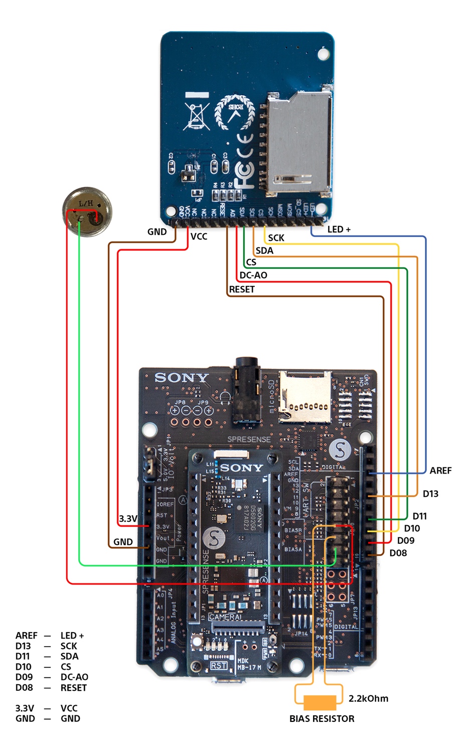
As can be seen on the schematics of the extension board the bias voltage is also provided directly to pins 5, 6, 11 and 12 on pin header JP10. So instead of soldering the bias resistors onto the board, they can simply be attached between the BIAS pin and the MIC_X pin. In this project only microphone channel A is used so it is enough to mount/attach one bias resistor.
Microphone Gain
Sometimes the microphone gain needs to be increased or adjusted to get the desired result. As for today there is no proper API call to do this but it can be done by editing the audio library file.
The audio library is located in the following places:
In Linux:
~/.arduino15/packages/SPRESENSE/hardware/spresense/1.0.2/libraries/
and in Windows:
%userprofile%/AppData\Local\Arduino15\packages\SPRESENSE\hardware\spresense\1.0.2\libraries\Audio
Open the file Audio.cpp and search for a function call to init_mic_gain:
init_mic_gain(input_device, 0)
Try to increase/change the integer value, test and check the result until you are happy with the result.
The TFT Display
The display used in this project has the st7735 TFT controller/driver chip. Data to the display from the Spresense board is transferred via a SPI interface.
A few more wires are needed, one to reset the display and power to the background LED light.
Above is a graphic schematic of how the TFT module is connected to Spresense. The Spresense is capable of running the SPI at a much higher frequency than the Arduino UNO. Running the SPI fast with long wires may result in unwanted behaviour of the display. So if this happens it can be good to try to lower the SPI frequency (in the TFT driver lib) and to shorten the wires between the TFT module and Spresense.
The drivers used for the ST7735 have been the standard TFT drivers in Arduino IDE, TFT for Arduino by Adafruit v1.0.6 ported to Spresense. The porting has mainly been to change the way CS and RS (DC/A0 in the schematic above) lines are being controlled. Details of the porting can be found on arduino-libraries account on GitHub.
The Code
The code to run this project consists of the main sketch that fetches the audio data stream via the Spresense audio library. A TFT st7735 software driver and it also requires a wav audio codec to be installed on the Spresense board. This will be in detail described in the Step-by-step instructions.
Step-by-Step Instructions
1. Install Arduino IDE, start it and install the Spresense board package.
2. Flash the Spresense bootloader if needed.
3. Fetch the source of this project from GitHub with the submodules: https://github.com/TE-KarlKomierowski/hackster_projects/.
$ git clone --recursive git@github.com:TE-KarlKomierowski/hackster_projects.git
4. Install the TFT drivers from the projects "arduino-lib" folder. This can be done in the Arduino IDE menu, "Sketch -> Include Library -> Add.zip Library...". Point to the folder spresense-audio-scope/arduino-lib/ and import TFT.
5. Open the sketch spresense-audio-scope/sketch/audio-scope/audio-scope.ino
6. Click "Upload" and you should see the audio waveform on the screen.


Comments
Please log in or sign up to comment.