


Hardware components | ||||||
 |
| × | 1 | |||
| × | 1 | ||||
 |
| × | 1 | |||
 |
| × | 1 | |||
| × | 1 | ||||
Software apps and online services | ||||||
| ||||||
Me and my teammate Divya made this project in our 6th semester as part of our FPGA course. We were given multiple choices but we wanted to do something new.
IntroductionIn this project, we will build an Air Quality Monitoring System using the Nexys-4-DDR and the MQ135 gas module. The goal is to use the XADC present in the Nexys-4-DDR to obtain ADC data from the MQ135 sensor and then display it on the multiple 7-segment displays on the board using a BCD to Binary converter. We have used the XADC IP from Vivado for this.
(image to be uploaded)
As you can see in the image the current AQI is being displayed verified from google weather.
(image to be uploaded)
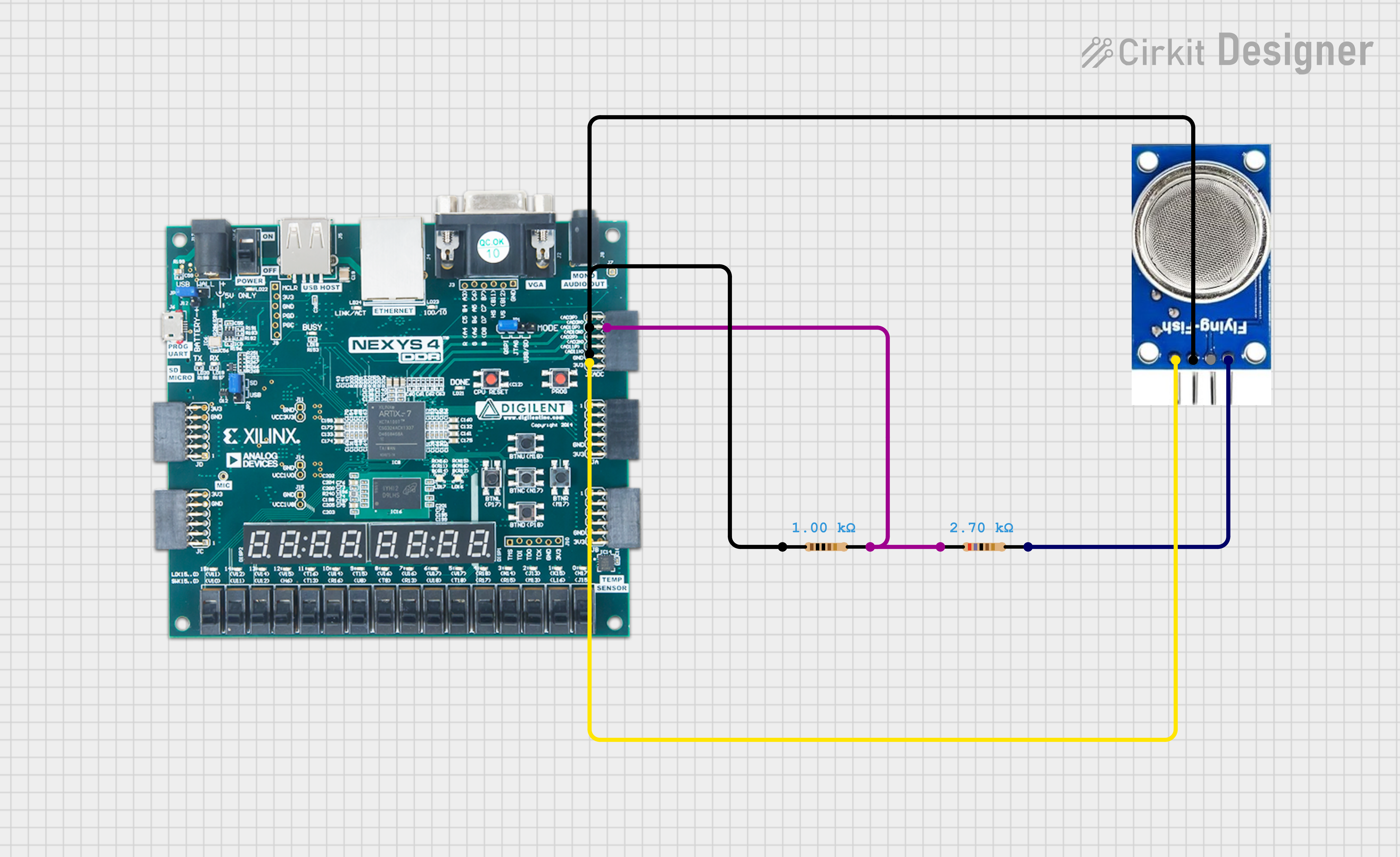
Hardware DesignThe hardware for this project consists of a Nexys-4-DDR FPGA board, an MQ135 gas sensor, jumper wires, a breadboard, and resistors. We need to build a voltage divider because the ADC pins on the Nexys-4-DDR are only 1V tolerant, so applying 3.3V would damage the board.
Nexys-4-DDRThe Nexys 4 DDR is a versatile FPGA development board designed by Digilent, featuring a Xilinx Artix-7 XC7A100T-1CSG324C FPGA and 128 MB of DDR2 SDRAM with a 16-bit bus. It includes clock sources like a 100 MHz crystal oscillator and allows for user-defined clocks via PMOD ports. The board provides robust connectivity options, including USB-JTAG for programming and communication, a USB-UART bridge, and a 10/100 Ethernet PHY (Microchip LAN). Additional features include an onboard power supply, a wide range of I/O options, and comprehensive expansion capabilities, making it suitable for a variety of applications in education, research, and development.
- XADC - The XADC (Xilinx Analog-to-Digital Converter) is an integrated feature in Xilinx FPGAs that provides dual 12-bit ADCs capable of sampling at up to 1 MSPS.
We can see from the schematic of the board that Xilinx have given a dedicated Pmod for XADC.
We will use AD10P and AD10N in this project.
- Seven Segment Display - The Nexys 4 DDR development board includes an eight-digit seven-segment display, which consists of eight individual seven-segment LEDs. Each digit can display numbers and limited alphabetic characters by illuminating combinations of the seven segments (labeled A to G). These segments are controlled by the FPGA through a series of pins, allowing for multiplexed control to drive all digits efficiently.
The MQ135 gas sensor module is a popular and versatile component used for air quality monitoring. It is specifically designed to detect a wide range of gases, including ammonia (NH3), nitrogen oxides (NOx), alcohol, benzene, smoke, and carbon dioxide (CO2). This makes it particularly useful in various environmental and industrial applications.
We have used XADC IP on FPGA to get analog value from MQ135.
How to Begin?Step 1 - Open Vivado app. I am using Vivado 2018.1
- create a new project.
- select RTL project and don't click on don't specify sources right now.
- Add sources create 2 files named main.vhd and binary_to_bcd.vhd
- Add constraint file named nexys-4-ddr.xdc
- Select Nexys4 DDR from boards column. If you cant see it then most probably you haven't installed it.
- Click on finish.
Step 2 - Copy files from my GitHub and paste them into the respective files. (I advise against cloning my GitHub repo because, due to different versions of Vivado, XADC IP might not work. I’ve tried this many times on different versions, so I know.'😒)
Step 3 - Go to IP catalog and search for XADC.
- Step 4 - Click on XADC and the window will appear.
Step 5 - Select the following options
- DRP in Basic (as we want to to change timing).
- Continuous Mode.
- All other things to not be changed.
- In ADC setup - Sequencer mode off.
- channel averaging none.
- channel for mux VP VN.
- Nothing to be ticked in Alarms(as we don't need them in this project)
- In single channel select VAUXP10 VAUXN10, channel enable tick, do not select rest
- check the summary. click ok.
- Next click on global. It will now take some time to build.
- daddr_in - A pdf from Xilinx told me about this. (I don't remember which one) which told that for AD10 0x1A is address of it.
- do_out(15 downto 4)- as our ADC is of 12 bits.
- dclk_in- use system clock.
Create a new text file named design.txt and copy and paste this code into it. Do not change anything. This code generates a waveform for a triangular wave when you run the testbench.
Now go back to Vivado.
- Right click on the IP you created and select Re-customize IP.
- In Basic scroll down go to Analog Sim File options and set them as following.
- Now add the Design.txt in Simulation Sources.
- Add sources. Add or create simulation sources. Add files. Files of type : All Files.
Now add testbench file to the project.
- Click on synthesis in Flow navigator (left tab).
- after it is complete you can run simulation-->Behavioral Simulation and run for 100ms.
- right click on ADCValidData and set it to Analog instead of digital.
- you will see something like this.
If you see this then it is correct.
Implementation and Bitstream GenerationRun Implementation and Bitstream Generation. If there is an error during Bitstream Generation, it means you have not mapped the I/Os properly or defined your clock correctly
Hardware Manager- Click on open hardware manager.(Make sure you have correctly connected the board to your PC)
- Click on open target and select auto-connect. It should now automatically connect to your board and then you can program it. 😁😊👌
Phew....😮💨. With this you have successfully made Air Quality System using FPGA board.
Thank you for reading this and don't forget to follow me and like and share this post with your friends, as will be sharing more projects related to Arduino, ESP32, Node-MCU, FPGA in the coming days.


Comments
Please log in or sign up to comment.