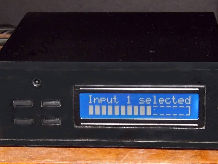
I have a 48” “Smart TV” but I really don’t like the sound of the tiny built-in speakers. I connected the TV audio output to my old analogue stereo hi-fi amplifier which drives some real speakers; sub-woofer, low, mid and high range with crossovers. It sounds much better than the TV speakers.
When I am watching cable TV programs, I can adjust the sound level with my cable remote controller, but when I am watching Netflix or YouTube movies on the internet I have no control. The sound level varies a lot between different shows and on YouTube, if a movie has commercials in it, the volume of those is sometimes almost deafening. I became so annoyed at having to get up from the couch to adjust the volume knob every time it this happened that I decided to do something about it. I built myself a remote stereo volume control.
What I choseThe only solid state dual attenuator chips I could find were overkill, with 80 steps of 1 db. I decided that I only needed about 20db attenuation in 1.5db steps. This would give me enough range with smooth transition between steps. I chose a fairly standard circuit for the attenuator with four switched stages of 1.5db, 3db, 6db and 12db. This gave me a total attenuation of 22.5 db in fifteen steps.
In my “spares” box, I had a blue OLED display which has two lines of sixteen characters that is perfect for displaying the fifteen levels of attenuation on a bar-graph with some custom characters. I also had some miniature 5V relays with double pole/double throw contacts which are just right for switching two channels of low level audio with very little loss and cross coupling.
I chose an Arduino Microprocessor to control my attenuator for simplicity and ease of programming. I used a VS1838 infra red detector from an old VCR to receive the remote IR signals. I took the metal shielding off it because I wanted it to be as sensitive as possible. The dome on it nestles in a 1/8” hole in the front panel. The output pin was connected to digital input 2 on the Micro and the + and – supply pins on the detector were connected to +5V and GND on the Micro.
What I didI downloaded the Infrared Remote library from Github and unpacked it into the Arduino libraries. In the IRLib2 examples I found a utility called “dump”. This tells you which protocol your remote uses and what the HEX code is that is received for each button you press on the remote. My cable remote uses GICable protocol so that is what I included in my program. I noted the codes for each of the buttons I wanted to use and for simplicity, I converted them to decimal values. The remote control that I used has a rather useful feature; if a button is held down, it will transmit the code for that button and then a series of “FFFF” codes. I used this to raise and lower the volume smoothly.
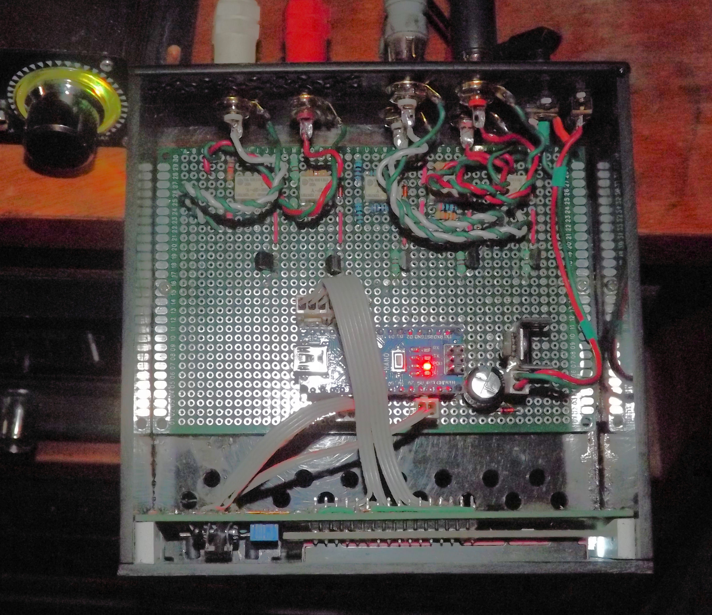
I drew up a circuit of what I needed to make it work. I had a spare relay and there was an unused digital pin on the Arduino so I added a relay to remotely select the input from either my TV or Radio. I designed the display on a separate circuit board connected to the main board with ribbon cables and Molex connectors so that it could be mounted vertically. I used an external 9volt, 300mA supply and included a 5V regulator on the main board to supply the five relays. The display is powered from the Arduino Micro 5V supply. It was necessary to add a 100uF capacitor across the 5 Volt supply on the display board to stabilize the display.
I included four small single contact push-buttons to manually control the volume and select the input. These were useful for de-bugging but now I never use them. If I made another one, I would leave them out.
I designed the two circuit boards as single sided printed circuits but I used the diagrams to build my version on double sided, 0.1”spaced prototype boards. There are several jumper wires on the main board. If you use double sided prototype board, make sure you use insulated wire for these so that they don’t short through the pads to the wires on the other side.
I made the case of 1/8” plastic sheet cut from an old plastic box. There are ventilation holes in the bottom and rear panel because the voltage regulator gets warm when all the relays are actuated at once. From the same plastic I made actuators to manually operate the small push buttons.


Comments
Please log in or sign up to comment.