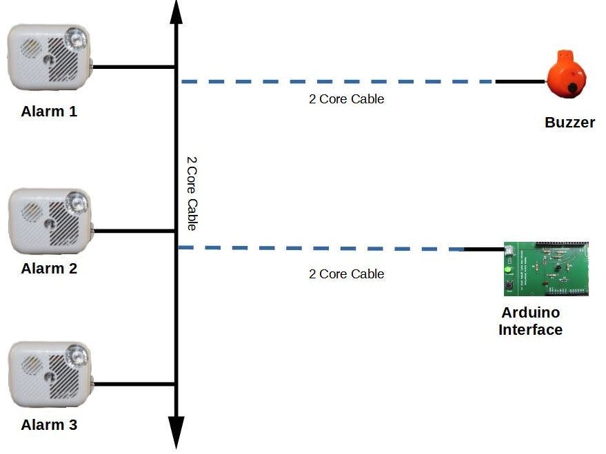
This project allows one or more Smoke Alarms to be monitored by an Arduino. It involves creating a Shield PCB and modifying a smoke alarm to connect to the shield. Also included is a remote buzzer that is activated by a Smoke alarm or the Arduino.
Features:- Monitor alarms from an Arduino Uno (e.g. it could send a text if the house isunoccupied)
- Alert occupant to an alarm that’s triggered in a distant/room/garage/attic
- Allow multiple smokealarms and buzzers to be connected together with a two core cable.
- Activate a remote buzzer from the Arduino (it may be monitoring e.g. water tank level)
- Modify an escape-light type smoke alarm to interface to an Arduino
- Create an Arduino Shield to interface to a Smoke Alarm
- Create a buzzer that can be sounded from the Ardhino or a Smoke Alarm
- Use an Arduino code example to monitor the alarms and sound the buzzer
- Additional info and optional buzzer constuction here: tek4um.com/smokeAlarm
The smoke alarm is modified by adding the components R9, Q1, R10 and a 2 pole JST connector shown in this diagram:
The other components shown, with the blue wiring, are an approximate diagram of the internal components of the Escape Light section of the smoke alarm.
Identify #1, #2 & #4 on the Kiddie i9080EU Smoke alarm as shown in this photo:
For this alarm the orange wire on the lLED was found to be connected to the +ve battery connector – marked (1) on photo. The other side of the LED then is (2). Using the multimeter, (4) is found to be ground (-ve on the battery).
If you have a different alarm type (it must have an escape light) then follow this procedure to find these connection points
1.1 - Only if you don't havetheKiddie i9080EU Smoke alarm:
If you have the Kiddie alarm proceed to 1.2
There are two 9 volt PP3 batteries in smoke alarms with an ‘Escape Light’ feature, here the connector is shown:
Find the connector that powers the Escape Light:
Disconnect one of the two batteries in the smoke alarm and press the smoke alarm’s test button. If the alarm sounds then that battery & connector is powering the smoke alarm and the other connector (the one we are looking for) powers the light. If the alarm doesn’t sound then swap connectors and try again. Make a note of with connector powers the escape light.
Remove both batteries and with proceed to check the lamp battery connector with a multimeter set to continuity beep.
Determine if the +ve (positive) terminal on the battery connector (red + in the Pic 3 below) is connected to one of the lamp connections. Use a multimeter set to continuity beep to find which lamp connector it is. Mark this connection as #1. Then other lamp connector is marked #2.
The other battery connector is ground (-ve) so mark it #4 as in the diagram. Note if you find that the +ve battery connecor is not connected to the escape light at all and instead it's the -ve battery connector then you will need a different modification - this is not described here so instead see the procedure here: http://tek4um.com/smokeAlarm/
1.2Solder on the wires & resistors for the BC237 PNP transistor.
Note the BC237 PNP transistor connections as in these photos:
1. Collector, red wire. series with R5 15Ω resistor
2. Base, yellow wire in series with R4 820Ω resistor
3. Emitter, red wire, no resistor.
Cover solder joints and resistors with heat shrink sleeving with a heat gun or the soldering iron.
1.3 Connect the transistor to the alarm
In the Alarm solder:
- Collector C to the Lamp battery +9 volt, #1 on alarm.
- Base B resistor to #2 -ve Lamp/LED
- Emitter E resistor to red on the new JST output connector #3, Red wire
- Output JST connector male black wire, #4, to the -ve of the battery (lamp battery)
2.1 Arduino Interface Circuit Operation:
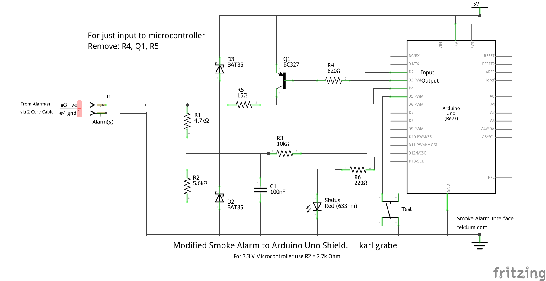
Arduino Pin D3 is set up in the code as an output. Pin D2 is an input. D3 is set to Low (not high) to sound the (optinal) buzzer. This causes current to flow through transistor Q1 base via R4 to ground. Q1 is now saturated on and its collector, connected to R5, goes high providing ~5 Volts at alarm connector #3. R5 provides some protection if there’s a short on the cable (not tested!).
The test push button is connected to input D5 and is used in the code to active the buzzer for testing purposes. D4 output is used to turn on the status LED, useful for testing.
2.2 Constructthe(optional) Buzzer Module
The Arduino can activate the Buzzer on pin 3 (see code)
Solder the components according to the buzzer module circuit diagram:
NOTE: these components are not listed in the hardware section as the buzzer module is optional. You will need the following PNP 800mA Transistor e.g. BC327, Resistors: 15Ω, 10kΩ, 82Ω, 820Ω, Zener Diode 5.1volt 500 mWatt BYZ885v1, Active Buzzer 5Volt, small project box - a cerial scoop is shown in the photos.
TheBuzzer module is fitted into a ‘easy scoop’ cereal cup, but anysimilar enclosure will do.
2.3 Wire up the System
3.1 The alarm status can now be read on an Arduino pin D2 as follows:
3.2 Asounding smoke alarm shows in the Arduino serial monitor:
Video of above:
Section 4 Sounding the Buzzer from the Arduino4.1 CodetosoundBuzzer
The code snippets below sound the buzzer for TEST_TIME_DURATION if the Test Button is pressed. The test button is connected to pin SMOKE_ALARM_TEST_BUTTON (see code).
Serial Monitor Output with test button pressed:
Video of the above:
4.2 Code could be added to monitor other events by connecting the Arduino to for example:
- Freezer Temperature e.g. if freezer temperature is too high
- Oil Tank level e.g. if below a certain leel
- Water Tank Level e.g. if too low or overflowing
- House Alarm system e.g. if triggered
- Outside temperature e.g. if freezing outside
The connections can be to any free input ports, and code written to sound the buzzer. It could be beeped different times depending on the alarm that has occurred.
5.0 Resources
Code, PCB files, photos, circuit explainations: tek4um.com/smokeAlarm/


_ztBMuBhMHo.jpg?auto=compress%2Cformat&w=48&h=48&fit=fill&bg=ffffff)


Comments
Please log in or sign up to comment.