


Hardware components | ||||||
_ztBMuBhMHo.jpg?auto=compress%2Cformat&w=48&h=48&fit=fill&bg=ffffff) |
| × | 1 | |||
 |
| × | 1 | |||
| × | 1 | ||||
| × | 1 | ||||
| × | 1 | ||||
Software apps and online services | ||||||
 |
| |||||
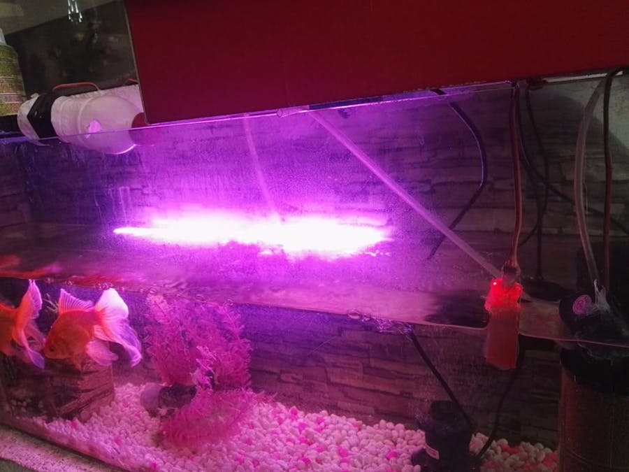
Here is a smart, controlled fishbowl for beginners with full description in the video. The ET fishbowl is a smart, controlled robot that automatically feeds your fish at a given time and controls the light, oxygen, filter, water level, and can add or remove water all by itself using Arduino + 1Sheeld.
Full instructions are provided in the following video:
Functions- Control light
- Control oxygen
- Control filter
- Auto-feeder (dropping fish food at a certain time)
- Add and remove water
- LCD display (read temperature and water level)
The auto-feeder is a really useful feature. You could use it if:
- You are forgetful
- Are busy and/or working all the time
- Are on vacation and need to feed the fish when you aren't there.
- Want the best care for your fishes.
All steps have been written in detail so as to make it as easy as possible for anyone to make this themselves!
Step 1: Materials and Project DetailsSkills Required:
- Experience with Arduino and electronics.
- Experience with coding.
Materials:
- An Arduino Board: I used ARDUINO UNO
- 1Sheeld board
- Smart phone
- Bulb
- 6 channel relay
- Fishbowl
- Filter
- Servo motor
- LM35
- power supply 24v DC
Download the Arduino application from the following link: https://www.arduino.cc/en/Main/Software. And download the 1Sheeld application onto your smartphone from the play store.
Step 3: Download 1Sheeld LibraryDownload the 1Sheeld Library from the following link: https://1sheeld.com/downloads/
Step 4: Extract 1Sheeld Library Files- Extract 1Sheeld library files
- Open Arduino libraries
- Make a new folder
- Rename it onesheeld
- Past extracted 1Sheeld library files on it
- TEXT_TO_SPEECH_SHIELD
- VOICE_RECOGNIZER_SHIELD
- GAMEPAD_SHIELD
- TERMINAL_SHIELD
- LCD_SHIELD
- SLIDER_SHIELD
- CLOCK_SHIELD
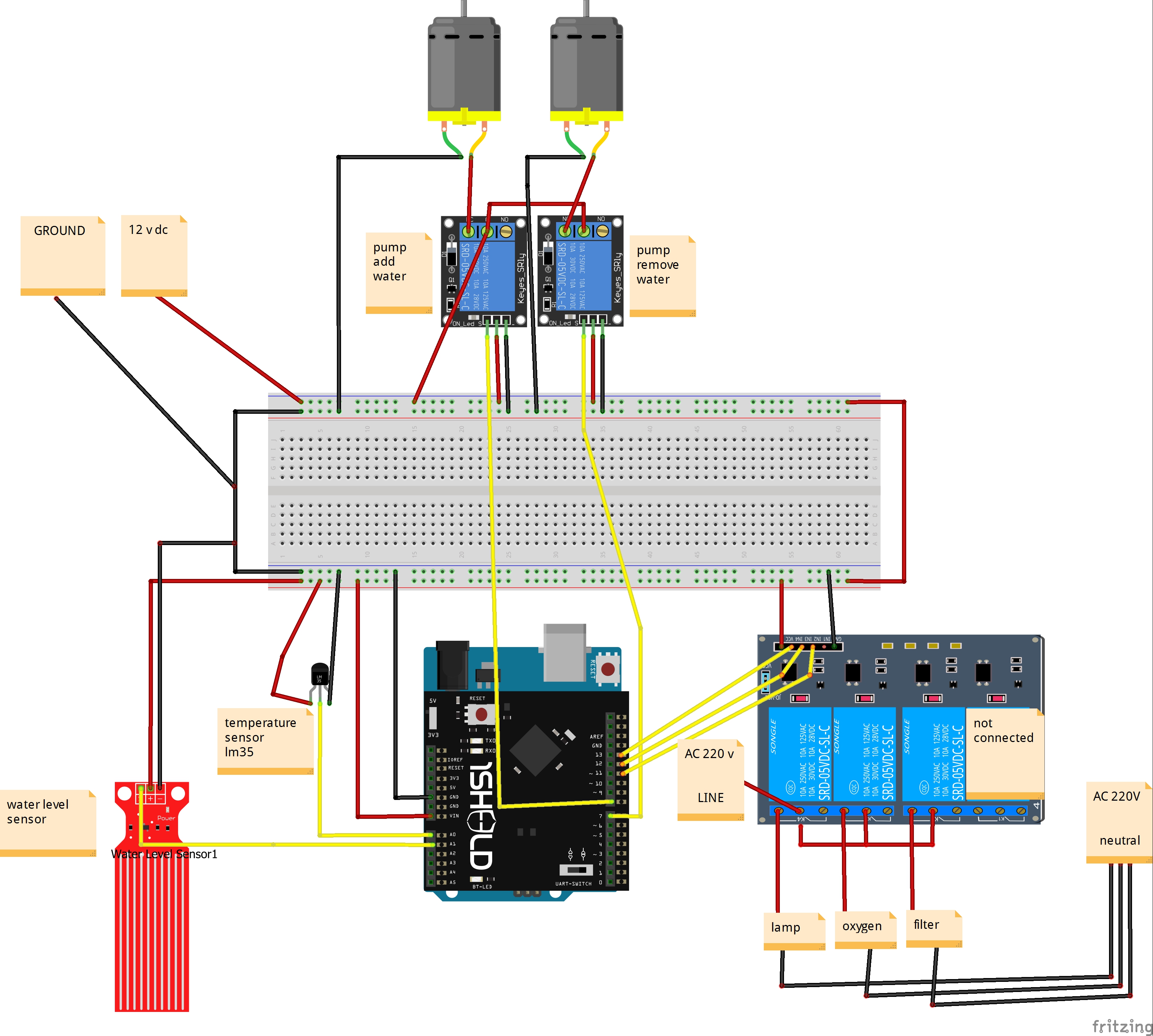
Initialize Arduino pins:
 int bulb_pin=13;               // connect relay_bulb to pin 13;
 int filter_pin=11;             // connect filter to pin 11;
 int oxygen_pin=4;              // connect oxygen_pin to pin 9;
Initialize Arduino pins as (INPUT OR OUTPUT):
 pinMode(filter_pin,OUTPUT);    // Set the filter_pin as output;
 pinMode(oxygen_pin,OUTPUT);    // Set the filter_pin as output;
 pinMode(bulb_pin,OUTPUT);      // Set the bulb_pin as output;
Using the Clock Shield
- Select the required shield from 1Sheeld application in smart phone. We must define it in Arduino:
#define INCLUDE_CLOCK_SHIELD
- We must select hour, minute and second in Arduino:
 hour = Clock.getHours();
 minute = Clock.getMinutes();
 second = Clock.getSeconds();
 if(hour == xx && minute == xx && second == xx) //change hours, minute,second to the desired time;
 {
// code                   //fully described in the code;
 }
if(hour == xx && minute == xx && second == xx )  //change hours, minute,second to the desired time;
 {
//code                    //fully described in the code;
 }
Using the Gamepad Shield
- Select the required shield from 1Sheeld application in smart phone. Define it in Arduino code:
#define INCLUDE_GAMEPAD_SHIELD
- Open and close filter using the Orange button and close it again using the same button.
 if ( (GamePad.isOrangePressed()) && (change_button_state_O==0) )
  {
open and close filter           / /  fully described in the code;
  }
- Open and close bulb using the Red button and close it again using the same button.
 if ( GamePad.isRedPressed() && change_button_state_R==0)
{
 open and close bulb      / /  fully described in the code
}
- Open and close oxygen using the Green button and close it again using the same button.
 if ( GamePad.isGreenPressed() && change_button_state_G==0)
 {
open and close oxygen         / /  fully described in the code
 }
Using { VOICE_RECOGNIZER_SHIELD} and {TEXT_TO_SPEECH_SHIELD}
- Select the required shield from 1Sheeld application in smart phone.
 #define INCLUDE_TEXT_TO_SPEECH_SHIELD
 #define INCLUDE_VOICE_RECOGNIZER_SHIELD
- Choose Voice commands:
const char firstCommand[]="hello";
const char secondCommand[]="control servo";
const char thirdCommand[]="turn on light";
const char fourthCommand[]="turn off light";
const char fifthCommand[]="turn on filter";
const char sixthCommand[]="turn off filter";
const char oxygen_openCommand[]="turn on oxygen";
const char oxygen_closeCommand[]="turn off oxygen";
const char seventhCommand[]="add";
const char eighthCommand[]="remove";
const char ninthCommand[]="yes";
const char tenthCommand[]="no";
- Set a certain individual function written by the user in the sketch to be called and run its functionality once a new command is given.
 VoiceRecognition.setOnNewCommand(&myFunction);
 void myFunction (char *commandSpoken)
 {
// control light, oxygen and filter using voice recognition     / /  fully described in the code
 }
Using the Clock Shield
- Select the required shield from 1sheeld application in smart phone. Define it in Arduino:
#define INCLUDE_CLOCK_SHIELD
- We must select hour, minute and second in Arduino:
hour = Clock.getHours();
minute = Clock.getMinutes();
second = Clock.getSeconds();
 if(hour == xx && minute == xx&& second == xx)  // change hours, minute,second to the desired time
 {
// code           / /  fully described in the code  (control servo position)</p><p>
 }
if(hour == xx && minute == xx && second == xx )
 {
//code           / /  fully described in the code   (control servo position)
 }
- Include servo library:
#include <Servo.h>
- Put a variable to store servo position:
int pos = 0; // variable to store the servo position
- Attach the servo on pin 9 to the servo object:
myservo.attach(9); // attaches the servo on pin 9 to the servo object
Using the Slider Shield
- Select the required shield from 1Sheeld application in smart phone. Define it in Arduino code:
#define INCLUDE_SLIDER_SHIELD
- Set a certain individual function written by the user in the sketch to be called and run its functionality once a slider position is changed giving a new value.
Slider.setOnValueChange(&servo);
- Put the following function outside the loop:
 void servo (byte sliderValue)
 {
 pos=sliderValue*90/255;       // scale convert from (0 to 255) to (0 to 90 degree)
 myservo.write(pos);          // tell servo to go to position in variable 'pos'
 delay(2);
}
We are using an LCD to show the degree of temperature and water level retrieved from the LM35 and water level sensors.
- Select the required shield from 1Sheeld application in smart phone. Define it in Arduino code:
#define INCLUDE_LCD_SHIELD
- Initialize temperature pin:
int tempPin = A0; // lm35 temperature sensor is connected to pin A0
- Initialize water level sensor pin:
int water_sensor = A1; // water level sensor is connected to pin A1
- LCD code:
 LCD.setCursor(0,0);              //Set the cursor to begin writing from the first row and first column.
 LCD.print("temp = ");
 int value = analogRead(tempPin);
 float mv = ( value/1024.0)*5000;
 float cel = mv/10;  LCD.setCursor(0,7);               // Set the cursor to begin writing from the first row and 8 column.  LCD.print(cel);                   // Print cel value
 LCD.setCursor(1,0);               // Set the cursor to begin writing from the second row and first column.
 LCD.print("water level= ");        // Print water level= .
 LCD.setCursor(1,12);             // Set the cursor to begin writing from the second row and column 13.  LCD.print( analogRead(A1));       // Print water level value .
We are using a pump to add and remove water.
Using the Gamepad
- Select the required shield from 1sheeld application in smart phone.
#define INCLUDE_GAMEPAD_SHIELD
- Add and remove water using the up and down arrows.
if(GamePad.isUpPressed())             // start adding water
   {
   //code       / /  fully described in the code</p><p>
   }
if(GamePad.isDownPressed())           // start removing water
  {
   //code       / /  fully described in the code
  }
- Stop adding and removing water using the Blue button.
if ( GamePad.isBluePressed() )           // stop adding or removing water
{
//code    / /  fully described in the code
}
Using the Voice Recognizer
This is fully described in the code.


Comments
Please log in or sign up to comment.