


Hardware components | ||||||
 |
| × | 1 | |||
 |
| × | 1 | |||
 |
| × | 1 | |||
 |
| × | 1 | |||
 |
| × | 1 | |||
 |
| × | 1 | |||
| × | 1 | ||||
 |
| × | 1 | |||
 |
| × | 1 | |||
| × | 1 | ||||
 |
| × | 1 | |||
 |
| × | 1 | |||
Hand tools and fabrication machines | ||||||
 |
| |||||
 |
| |||||
For my senior design project, I am working with my team to create a bed-rest rehabilitation system to allow patients to combat muscle atrophy and cardiovascular complications during post-operative recovery. This data-tracking project will serve as a subset of this rehabilitation system to facilitate tracking of patient activity to facilitate patient motivation and accountability. This will also allow physicians/therapists to analyze data and effectively track patient progression to ensure patients do not face muscle atrophy or cardiovascular complications and can be discharged from the hospital in a shorter time frame.
Overview:After starting up this tracking system, the user can flick the switch to turn on data tracking. Once data tracking is enabled, the user can perform an exercise of their choice with the data-tracking system attached to a moving component. When an exercise rep is performed, a green LED will blink to indicate to the user that they successfully completed a rep. Furthermore, the 16x2 LCD display will display the total rep count so the user can easily see and recall their rep count. The switch can be flicked off and then back on to reset the rep count for a new exercise set.
Setting Up the PocketBeagle1) Flashing the PocketBeagle
Download the following file: bone-debian-10.11-iot-armhf-2022-02-03-4gb.img.xz
With a programmable SD card inserted into your PocketBeagle, use an SD card flasher like Etcher to flash the PocketBeagle with the file.
2) Installing Libraries
Follow the instructions on this page to connect your PocketBeagle to the internet
Check out the project's README file for step-by-step instructions on installing the required libraries and dependencies
Build Instructions1) Breadboard Setup
- Connect the ground rails on the breadboard to the ground on the PocketBeagle (P1_16)
- Connect both positive rails on the breadboard to the SYS 3.3V on the PocketBeagle (P1_14)
- Connect a positive rail on the half-sized breadboard to SYS VOUT on the PocketBeagle (P2_13)
2) Switch
Connect the switch to the breadboard and then wire it to the PocketBeagle as shown in Figure 1. The pullup resistor (1k ohm) should be connected to the ground rail. The jumper wire to the GPIO pin (GPIO59, P2_2) should be connected to the button in parallel with the pullup resistor.
3) LED
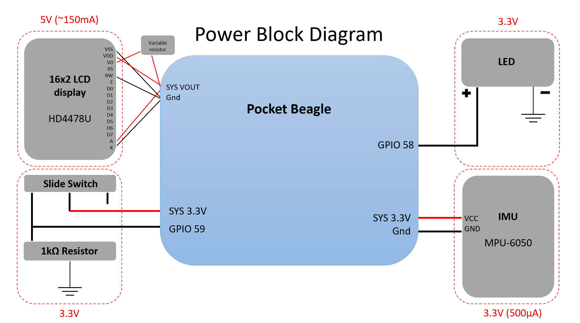
a. Connect the LED to the PocketBeagle as shown in Figure 2. The anode (+, long lead) should be connected to the GPIO pin (GPIO 58, P2_4) and the cathode (-, short lead) should be connected to ground.
4) IMU (MPU-6050)
The connections on the IMU should have headers soldered in to facilitate attachment to the breadboard, as shown in Figure 3. To power the IMU, the VCC pin on the IMU should be connected to the 3.3V power rail on the breadboard and the GND pin on the IMU should be connected to the ground rail on the breadboard. To collect data from the IMU, connect the SCL pin on the IMU to SCL on the PocketBeagle (I2C1, P2_9). To collect data from the IMU, connect the SDA pin on the IMU to SDA on the PocketBeagle (I2C1, P2_11). The pin connections are depicted in Figure 4. This figure also shows an LED on the MPU-6050 verifying that it is being powered appropriately.
5) 16x2 LCD Display (HD4478U)
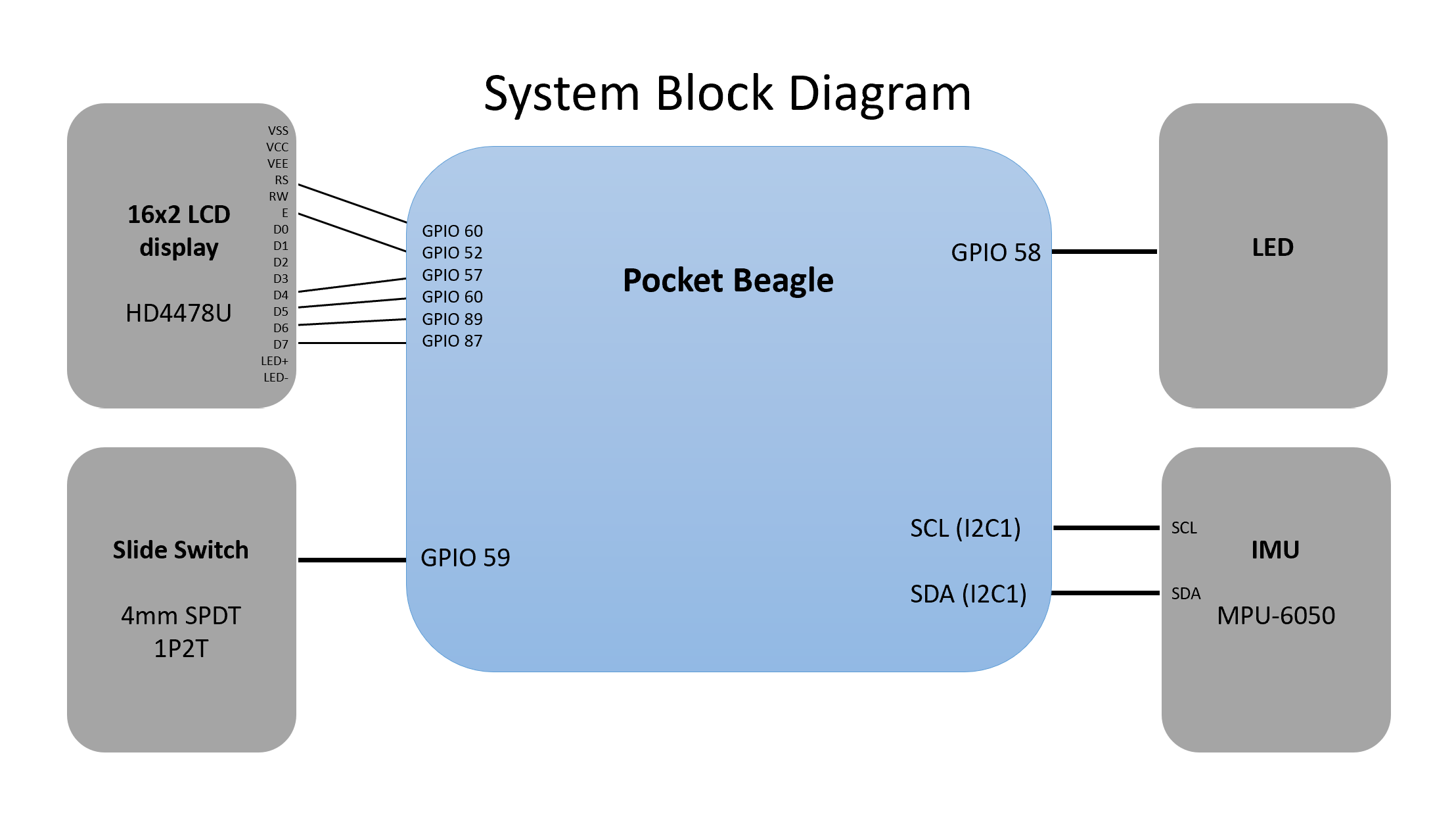
The 16x2 LCD display comes with headers attached to facilitate breadboard attachment. The 16x2 LCD should be powered by connecting the following pins to the ground rail: VSS, RW, and K, and the following pins to the SYS VOUT (5V) power rail: VDD, V0, A. V0 should be connected to the SYS VOUT (5V) power rail through a variable resistor. The variable resistor can be tuned to alter the adjust the character's display contrast. Connections to the pocket beagle for data transmission involve 7 GPIO pins connected to RS, E, D4, D5, D6, and D7 on the 16x2 LCD display. These connections are shown in Figure 5. The exact GPIO pin connections are elucidated in the System Block Diagram in the Schematics section.
Comments
Please log in or sign up to comment.