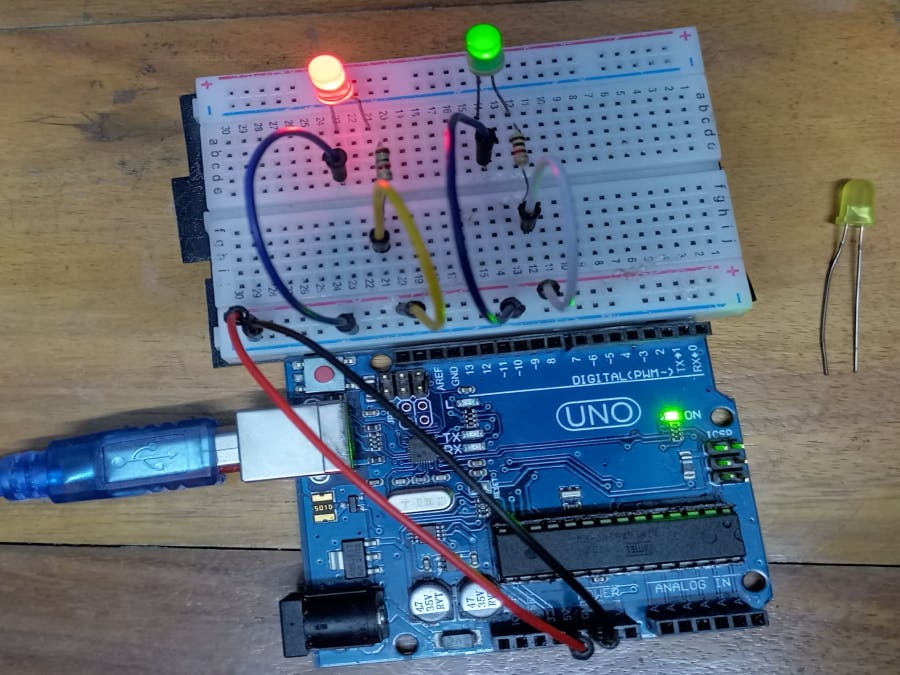
This is the very basic project on Arduino. This is actually the beginning of the journey of Arduino learning. We can build up many interesting projects by the help of Arduino. Here we are going to discuss how we can take power from the Arduino board and ON the two LED lights.
Components1. Arduino UNO
2. Breadboard
3. LED Light
4. Resistor (220ohm)
5. Jumper Wire (Male-Male)
What is Arduino?According to arduino.cc --> Arduino is an open-source electronics platform based on easy-to-use hardware and software. We can do many fascinating things using Arduino. Arduino has different types of boards like Arduino UNO, Arduino Mega, Arduino Due, Arduino Nano, Arduino Leonardo etc. It is actually circuit board where different types of electronic component are attached with a micro-controller. Arduino UNO is very popular boards among the all boards. The fun fact is that Arduino is open-source. So, anyone can change the code and design the Arduino boards according to their needs.
More on -----> https://www.arduino.cc/en/Guide
Arduino UNOArduino UNO is the most frequently used Arduino board. Arduino UNO depends on ATmega328P based microcontroller. This is very simple to learn. It consists 14 Digital I/O pins and 6 Analog pins. Form the 14 digital pins there are 6 PWM pins also available. These PWM pins can be used as Analog pin.
Arduino UNO Specification- Microcontroller: ATmega328P
- Operating Voltage: 5V
- Input Voltage Limit: 6-20V
- Input Voltage (recommended): 7-12V
- Digital I/O Pins: 14 (D0-D13)
- PWM Digital I/O Pins: 6 (D3, D5, D6, D9, D10, D11)
- Analog Input Pins: 6 (A0-A5)
- DC Current per I/O Pin: 40 mA
- DC Current used for 3.3V Pin is 50 mA
- Flash Memory: 32 KB, and 0.5 KB memory is used by the boot loader
- Clock Speed: 16 MHz
- Length: 68.6 mm
- Width: 58.4 mm
- Weight: 25 g
Arduino integrated environment is a software where we can write, test and upload code in the Arduino boards. Programs has written using Arduino IDE are called as sketches. We can write code here & after writing the code we can verify the coders are right or wrong. The code also loads on Arduino boards by using this IDE. This IDE has also a text console where we can print several values for the testing purpose to see that our designed circuit gives us the desired value or not.
A breadboard is used to design and test the circuit. In a breadboard we can connect electronic components like led, resistor, sensors etc without solder to make a circuit while using breadboard. It is easy to connect equipment with the breadboard.
Here, A & D are two power rails. Red one indicates that we need to connect the positive terminal of battery or any kinds of power supply. The power rails is horizontally short from one point to another point. B & C are the circuit building area. These two sections are separated by each others. In B section vertical lines are short from one point to another point. That means 5 points are individually short in the vertical direction. 24 lines are individually short in vertical direction. In the C section also 24 lines are individually short in the vertical direction.
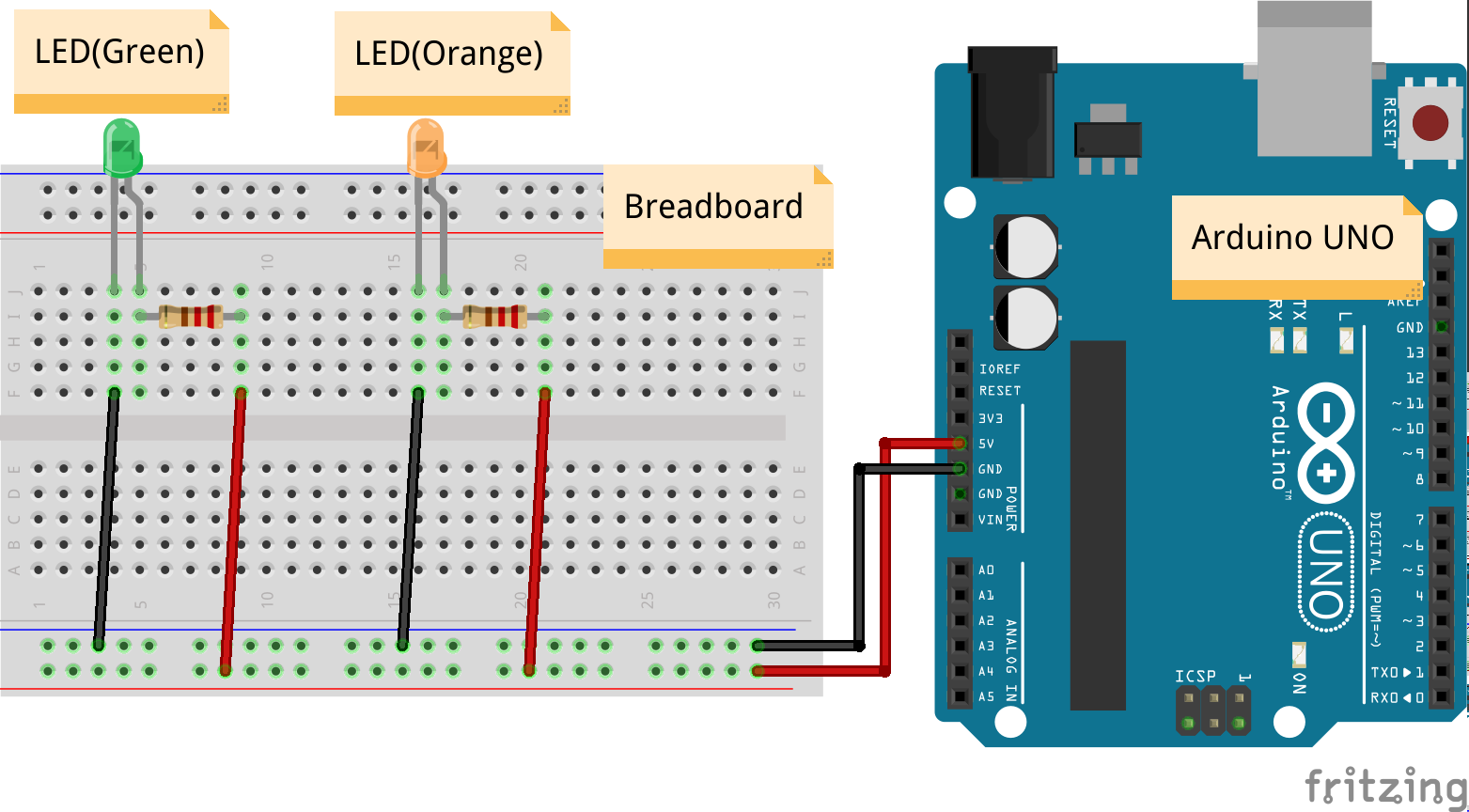
Discussion on CircuitFrom the schematic diagram we can see that the two led(Green and Orange) are connected with power rail via a 220ohm resistor. Here, resistors are user for the protection of the led lights. These 2 led's Anode is connected with the resistor and Cathode is connected with the negative terminal of power rails of breadboard.
Here, Arduino Board is used only for the power supply. By using Arduino we can supply 5V to anywhere. So, here from Arduino 5V is supplied to the breadboard. We can measure the voltage by using a multimeter.
So, when we turn ON the arduino that means when we power up the Arduino UNO board we will get the 5V supply in the breadboard instantly. Then the power will go through the LEDs through resistor. Here a the 5V willl not flow through the LEDs because of the voltage drop for the resistors. Finally the leds will lit up.
In this project we did not use any Arduino coding.Demonstration VideoLinks
This project Github Repository Link: https://github.com/MakerBuddy/arduino-basics-projects/tree/main/Project-%231
This Project Tinkercad link: https://www.tinkercad.com/things/a2uewoD0RVO


_ztBMuBhMHo.jpg?auto=compress%2Cformat&w=48&h=48&fit=fill&bg=ffffff)


Comments
Please log in or sign up to comment.