


Hardware components | ||||||
| × | 7 | ||||
 |
| × | 1 | |||
| × | 1 | ||||
| × | 1 | ||||
| × | 1 | ||||
| × | 1 | ||||
Hand tools and fabrication machines | ||||||
 |
| |||||
I use LEDs in plenty of projects and art pieces. I've been caught a couple of times by a bad LED so I like to test them first. Now I know there are plenty of ways to test LEDs. Well, here's one more.
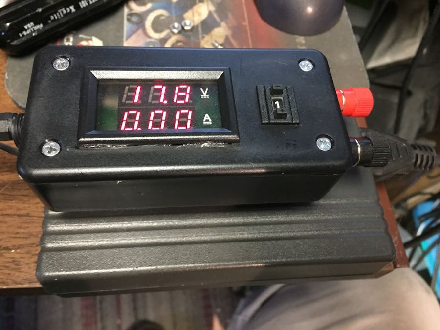
It also good for testing small electronic devices of unknown condition. It's essentially a current limiter with a digital panel meter.
Step 1: Making a Nice Case the CNC wayI got fancy and used a CNC to cut out the front panel to hold the meter and the switch. A Dremel works just fine too. I'm a little dangerous free-handing with a Dremel, so that's why I got the CNC. I do this with many of my projects. You can even engrave legends and logo's this way.
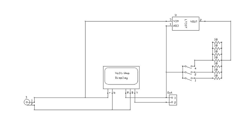
I used a Compaq 16V laptop supply since I had a few lying around. The meter operational power input is rated for 5-30V, so keep that in mind when picking your supply. I attached the meter power directly to the input. You could add a Zener diode in series with the meter supply lead to raise the limit a bit to handle 36V input. The meter range itself is 0-100V, so a separate and isolated meter supply would allow you to use the full range.
Step 2: Simplistic DesignI assembled mine in a Radio Shack project box. Most people use a potentiometer for variable current control. I took a different approach. I had these SCSI address selector switches in the junk drawer. Using a bunch of 10 ohm resistors I made a simple selector. The output current will be the value of the switch times 100Ma.
Some of these switches have stop pins that block certain positions like 0 or 7 and beyond. The stop pins can usually be removed or just relocated. My switches go from 1 to 7 by default so I left them alone.
You could extend this to use BCD or HEX switches by adding another bunch of resistors.
Step 3: Testing an RGB LEDI tested a few RGB LEDs. It's nice to be able to check the forward voltage of each section, too. Sometimes I cheap out and use series resistors in my LED drivers rather than current sources. This way I can select the right resistors for each section.
I tested all sections at the 200Ma setting. The RED section was about 7V. The Green was about 9.5V and the Blue was almost 10.5V.

Comments