COVID-19 health: Remote, distanced, glass walled
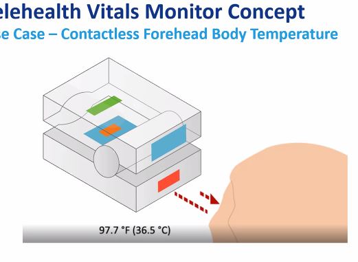
project focus is on Telehealth and monitoring
parameters :
* Temperature, Oxymeter
* Visual signs - AI image - analysis, ML,DL
* Voice detection (concepts)
* breath detection(concepts)
* social distance(concepts)
Programmable for updates and quick implementation.
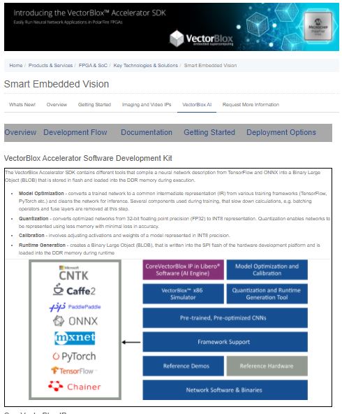
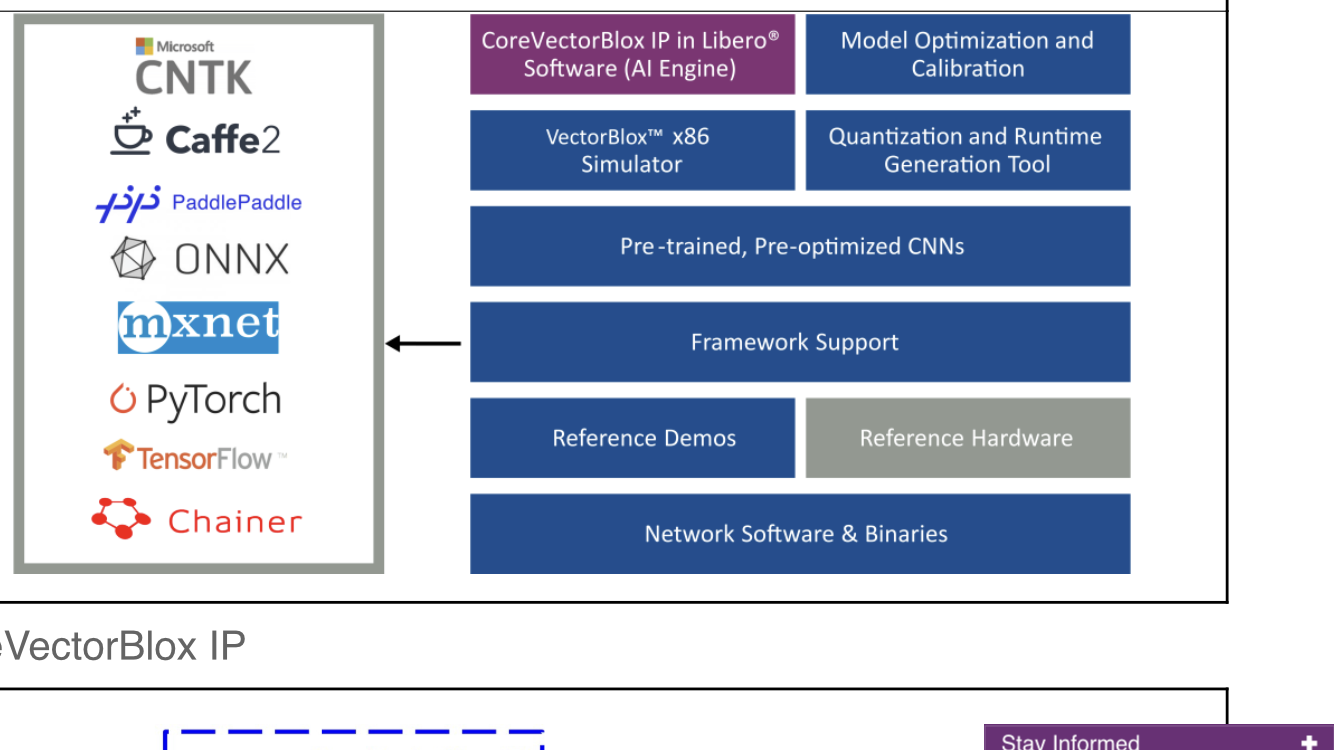
The CNNs can also updated online instantaneously.
-----------------------
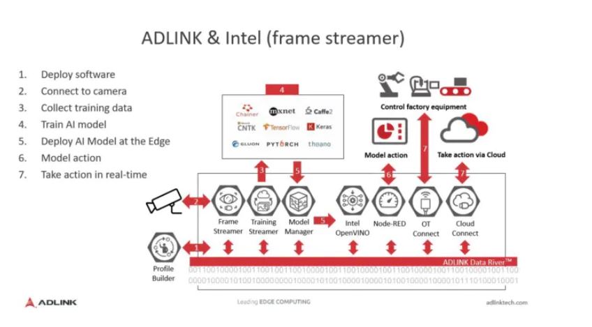
The AI real product requires echo system of Hardware and Software.
Initial focus is on selected applications like oxymeters and AI applications
===============================================================
OXYGEN monitors: References :
The covid19 affects mostly to the lungs with effects on oxygen circulation.
Two most measured are spo2 and pao2. The relations are shown in the graph.
Spo2 is measured using oxymeter externally . Pao2 require blood drawn.
There are many documents describing them in reference.
Concepts for oxygen monitor at whole body
============================================
Normal breathing for oxygen is important during covid cases.
When there is problem, the oxygen at blood stream falls down.
Oxymeter in recent days/years is common to measure at finger tip.
The oxygen concentration Spo2 and Pao2 are interrelated as shown
by many articles and tests. Current pao2 measurements require blood
drawing from artery and lab tests.
The oxymeter can be used at other parts of the body to monitor
any blood oxygen issues due to blood clots. Current use of oxymeter
is limited to finger tips. It uses the light emit and capture in dark
covered area.
The device environment need to be modified to use it around arms near
artery. Similarly it can be used at/near heart, neck and legs.
This may also need to be calibrated similar to temparature measurments
at different parts of the body.
----------
Observations/calculations:: Reference to Graphs:
For the first 10% reduction in SpO2 from 100% to 90%, decrease PaO2 by 4 mmHg for every single percent reduction in SpO2 with a resultant PaO2 falling from 100 to 60 mmHg [Table 1]. For the next 10% reduction in SpO2 from 90% to 80%, decrease PaO2 by 1.5 mmHg for each percent reduction in SpO2 which will result in PaO2 falling from 60 to 45 mmHg. Finally, for SpO2 levels below 80%, divide it by 2, that is half the value of SpO2, and we get the requisite PaO2 level
Spo2 measurements can be extended to other parts of the body.
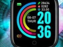
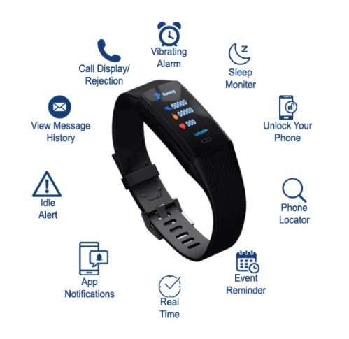
Using wearables at wrist as watch . Blood pressure kind of wrappers for
Femoral artery.
Artery where spo2 measurement can be extended : Femoral artery
======================================================================
======================================================================
Prototype implementation : High level descriptions.
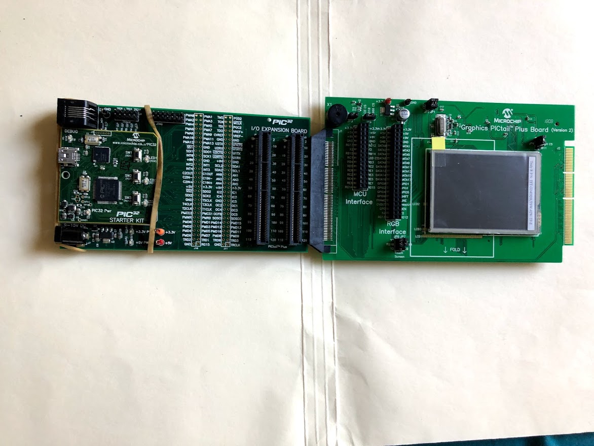
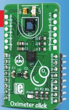
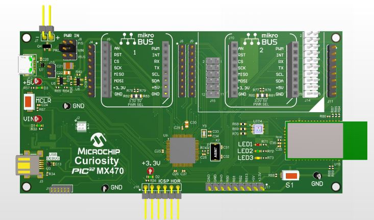
Following microchip curiosity board supports two Mikroe click boards.
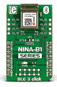
Using one for Bluetooth and another for oximeter. Together it can be used
for prototyping many telehealth sensors.
More deteails can be found at different sections. Focussing more on one application of Oxymeter.
Assembled main board with stack click boards.
Microchip and MIKROE partnership supports.
Included data below for quick one place for all references.
--------------------------------------------------------------------------------------------------------------------
Oximeter support from MIKROE : Reference :
SOFTWARE SUPPORT - OXYMETERWe provide a library for the Oximeter Click on our LibStock page, as well as a demo application (example), developed using MikroElektronika compilers. The demo can run on all the main MikroElektronika development boards.
Library Description
The library can communicate with the device via I2C driver by writing to the registers and by reading from the registers, including data registers. The library has the ability to measure the level of oxygen (O2) in the blood, something like blood pressure. Library also can configure the device to works in two Time Slot Mode independently with different configurations. For more details check the documentation.
Key functions:
uint8_t oxim_writeReg( uint8_t register_address, uint16_t transfer_data )- The function writes 16-bit data to the register.uint8_t oxim_setTimeSlotA( uint8_t enableSlotA, uint8_t enablePhotodiode, uint8_t enableLED, uint8_t setMode )- The function performs the configuration for Time Slot A and enables the interrupt for this Slot.uint8_t oxim_enableChannels( uint8_t selectChannel )- The function determines which channel/channels be enabled.void oxim_readData( uint32_t *channResults, uint8_t resultMode )- The function reads data in the desired mode for determined Slot.
Example description
The application is composed of three sections :
- System Initialization - Initializes peripherals and pins.
- Application Initialization - Initializes I2C driver and performs the device configuration which puts Time Slot Ain enabled mode and LEDX2 (IR diode) to the active state. On Oximeter click the photodiode is connected on PD1 input, and because we will observe the Channel 1 in this example (CH1 is enabled). Before the device configuration, the SW reset will be performed and in this way, we will put the registers in the initial state.
- Application Task - (code snippet) - Gets data when IR diode (LEDX2) is enabled, and after that gets data when LED diode(LEDX1) is enabled. Repeats operation 10 times and then calculates the average value for both results. The results are sent to the serial port, to be displayed as a graph by the application. Note: For this example, you must have the serial plot application. The IR diode is internally connected on LEDX2 input, and the LED diode is internally connected on LEDX1 input. The photodiode is internally connected on PD1 input. When we want to perform some register configuration we must first put the device in Program Operating Mode, then we can set the desired register to the desired value, and when we finished, then we can put the device back to the Normal Operating Mode.
void applicationInit()
{
 oxim_i2cDriverInit( (T_OXIM_P)&_MIKROBUS1_GPIO, (T_OXIM_P)&_MIKROBUS1_I2C, 0x64 );
 Delay_ms( 300 );

 oxim_reset();
 oxim_writeReg( _OXIM_SAMPLE_CLK_REG, 0x0080 );
 oxim_setMode( _OXIM_DEV_PROGRAM_OP_MODE );
 oxim_setTimeSlotA( _OXIM_EN_SLOT, _OXIM_PD1_PD2_PD3_PD4_CONN, _OXIM_LEDX2_EN, _OXIM_SLOT_NORM_OP_MODE );
 oxim_setTimeSlotB( _OXIM_DIS_SLOT, _OXIM_PD1_PD2_PD3_PD4_CONN, _OXIM_LEDX1_EN, _OXIM_SLOT_NORM_OP_MODE );
 oxim_enableChannels( _OXIM_CH1_EN );
 oxim_writeReg( _OXIM_STATUS_REG, 0xFFFF );
 oxim_writeReg( _OXIM_DATA_ACCESS_CTL_REG, 0x0000 );
 oxim_setMode( _OXIM_DEV_NORMAL_OP_MODE );

 mikrobus_logWrite( "Oximeter is initialized", _LOG_LINE );
 mikrobus_logWrite( "", _LOG_LINE );
 Delay_ms( 300 );
}
Additional Functions :
- void oxim_plotDisplay() - Makes the average value of 10 samples when IR diode and LED diode is enabled alternately and logs results on the serial port in a form of a graph.
- void oxim_uartDisplay() - Gets 100 samples of data when IR diode is enabled, and then gets 100 samples of data when the LED diode is enabled and after that logs this 100 samples of data for both diode parallel on USB UART as graphics view.
- void oxim_logsResults() - Gets data which is determined in application INIT configuration and logs result on USB UART.
The full application code, and ready to use projects can be found on our LibStock page.
Other mikroE Libraries used in the example:
- Conversions
- I2C
- UART
Additional notes and information
Depending on the development board you are using, you may need USB UART click, USB UART 2 click or RS232 click to connect to your PC, for development systems with no UART to USB interface available on the board. The terminal available in all MikroElektronika compilers, or any other terminal application of your choice, can be used to read the message.
MIKROSDKThis click board is supported with mikroSDK - MikroElektronika Software Development Kit. To ensure proper operation of mikroSDK compliant click board demo applications, mikroSDK should be downloaded from the LibStock and installed for the compiler you are using. For more information about mikroSDK, visit the official page.
BLUETOOTH (BLE) supports :
SOFTWARE SUPPORT - BLUETOOTHWe provide a library for the BLE 7 Click on our LibStock page, as well as a demo application (example), developed using MikroElektronika compilers. The demo can run on all the main MikroElektronika development boards.
Library Description
This library offers a choice to communicate with the BLE 7 Click board (BGX 13P22GAV21 module). Library can send commands, configurations, status request, pairing request or any other data. Also can receive any response from the BGX module, including confirmed or unconfirmed response (answer), module status, connection status, and any transferred data from the other BGX module. Any BLE 7 click can be configured to work as central (server, master) device or as peripheral (client, slave) device. For more details check documentation.
Key functions:
void ble7_uart_isr( void )- This function reads response bytes from the BGX module and sets flag after each received byteuint8_t ble7_response_ready( void )- This function checks does response ready or not.void ble7_send( uint8_t *tx_data )- This function allows user to transmit data to the BGX module.
Examples description
The application is composed of three sections :
- System Initialization - Initializes peripherals and pins.
- Application Initialization - Initializes UART serial interface, uart interrupt, and executes the module reset.
- Application Task - (code snippet) - This function has two segments. First segment allows user to enter a commands, module configuration, data which will be transmitted, also to check all module and connection status by using the serial terminal. Press 'enter' when you want to send the entered command (data). Press 'backspace' to delete the wrong entered character before you send the command. Press 'up-down' or 'left-right' to see and enter the 3 last sent commands. Second segment allows user to check and get response from the module when response was ready. Note : The all possible commands and module configurations can be found on the next link: https://docs.silabs.com/gecko-os/1/bgx/latest/commands
void applicationTask()
{
    rx_data = UART_Rdy_Ptr();

    if (rx_data != _RX_NOT_READY)
    {
        rx_data = UART_Rd_Ptr();

        checkRX();
    }

    logRsp();
}
Additional Functions :
- _strcpy - Allows user to copy content of one string to another string, starting from the first place.
- prevCmd - Checks which character (up, down, left, right) was entered by the user.
- checkPrevCmd - Determines which of the 3 previous commands will be entered again.
- checkRX - Checks which character was entered by the user and executes a operation which is determined with the entered character.
- getRsp - Catches the response bytes and sets flag when the response was ready.
- logRsp - Allows user to see and check the response on the serial terminal.
- interrupt - Checks does any new byte was received from the module.
The full application code, and ready to use projects can be found on our LibStock page.
Other mikroE Libraries used in the example:
- UART
Additional notes and informations
Depending on the development board you are using, you may need USB UART click, USB UART 2 click or RS232 click to connect to your PC, for development systems with no UART to USB interface available on the board. The terminal available in all MikroElektronika compilers, or any other terminal application of your choice, can be used to read the message.
MIKROSDKThis Click board™ is supported with mikroSDK - MikroElektronika Software Development Kit. To ensure proper operation of mikroSDK compliant Click board™ demo applications, mikroSDK should be downloaded from the LibStock and installed for the compiler you are using.
For more information about mikroSDK, visit the official page.
mikroBUS™ Standard specification
=======================================================================
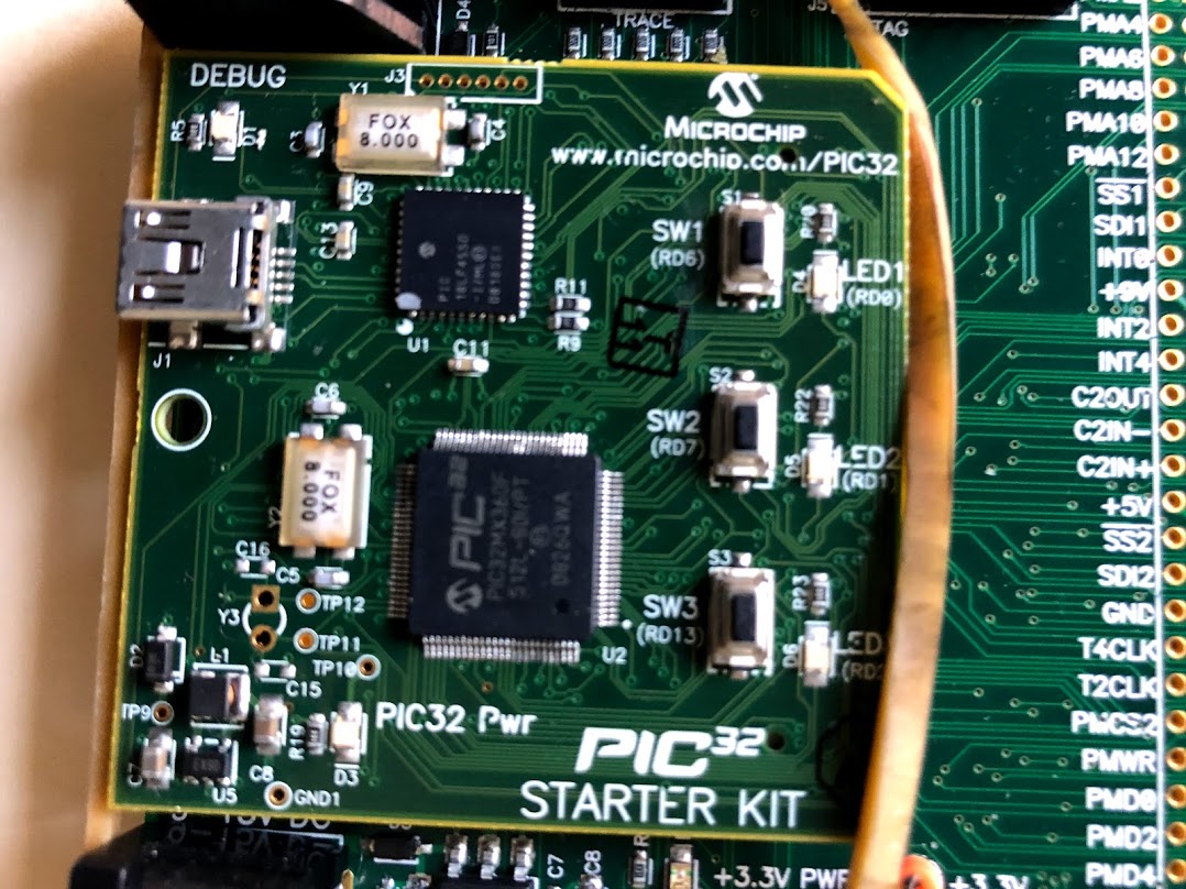
PIC32 MPLAB IDE
* setups
* Project code runs
------------------------------------
google cloud experiments for AI :
References : Conclusions
* There are many references.
* There are some more as part of attachments and Things
* Microchip has its own Oximeter prototype
* Pao2 measurements are CO meters. They are calibration tools for Spo2
* Pao2 measurements are invasive type while Spo2 is non-invasive.
* Standard Disclaimers apply. All references are for the explanations only.
* There are simulators which make it possible to have display work identically on desktop , mobile and wearable.
* AI techniques , machine vision , inferencing trials are made on google Colab and cloud.
* Good Luck !!




Comments