


Hardware components | ||||||
_ztBMuBhMHo.jpg?auto=compress%2Cformat&w=48&h=48&fit=fill&bg=ffffff) |
| × | 1 | |||
 |
| × | 1 | |||
 |
| × | 1 | |||
 |
| × | 1 | |||
| × | 1 | ||||
 |
| × | 4 | |||
 |
| × | 1 | |||
 |
| × | 1 | |||
 |
| × | 1 | |||
Software apps and online services | ||||||
 |
| |||||
Read more
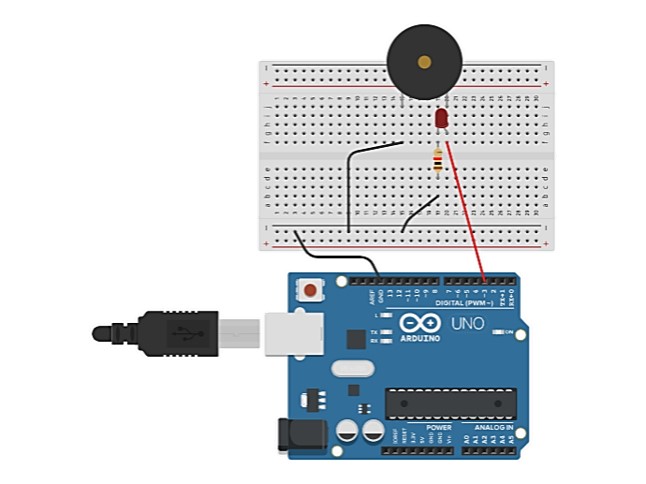
Breadboard Diagram
Make the connections as shown in the figure above.
Piezo: J15 and J20 (breadboard)
LED: Anode and Cathode to g20 and g19 respectively on the Breadboard.
Resistor: f19 and d19 on the breadboard.
Jumper wire (red): connecting the PIN3 (of Arduino) and f20 (of breadboard)
Jumper wire (black): connecting the GND (of breadboard) and -ve (of breadboard)
Jumper wire (black): connecting f15 (of breadboard) and -ve (of breadboard)
Jumper wire (black): connecting b19 (of breadboard) and -ve (of breadboard)


Comments
Please log in or sign up to comment.