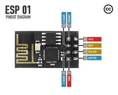
The ESP8266 (ESP-01) is a WiFi module running at 3.3V, so it normally requires a 3.3V TTL level USB to Serial port adapter, for serial connection from a PC.
This writeup shows how a compatible MCU can be used as a serial proxy or serial passthrough, to forward USB traffic from the PC to the ESP8266. And of course returning traffic from the ESP8266 back to the PC.
The solution is to use an Arduino MKR series, Arduino Zero or compatible, based on SAMD21 or SAMD51 MCU’s with at least 8 Kbytes of SRAM and 16 Kbyte of flash, working at 3.3 volt. A special Arduino sketch must be flashed on the microcontroller.
The MCU should use native USB for PC connection and a hardware UART for connecting to the ESP. The Arduino SAMD21/51-based MCU’s fulfill these requirements.
This writeup is primarily meant for flashing new firmware on the ESP, but may also be used to watch bootloader messages or execute AT-commands on the ESP from the Arduino Serial Monitor or using a terminal emulator with serial port support.
Connect the ESP8266 (ESP-01) to the Arduino like this:
Pin 8, 9 and 10 might be replaced with other pins, just remember to change the definitions in the Arduino sketch.
Software setupInstall the Arduino sketch from https://github.com/ksmith3036/EspSerialPassthrough using Arduino Studio or Visual Micro into the Arduino MKR or compatible,
Firmware from EspressifFirmware may be found at https://www.espressif.com/en/support/download/at.
Content of firmware downloaded from espressif:
Filename                                                    Size
Fwfolder\.DS_Store                                          8196
Fwfolder\ESP8266 NonOS AT Release Note.pdf                117598
Fwfolder\bin\.DS_Store                                     10244
Fwfolder\bin\blank.bin                                      4096
Fwfolder\bin\boot_v1.7.bin                                  4080
Fwfolder\bin\esp_init_data_default_v08.bin                   128
Fwfolder\bin\at\.DS_Store                                   8196
Fwfolder\bin\at\README.md                                   2182
Fwfolder\bin\at\1024+1024\user1.2048.new.5.bin            413444
Fwfolder\bin\at\1024+1024\user2.2048.new.5.bin            413444
Fwfolder\bin\at\512+512\user1.1024.new.2.bin              413444
Fwfolder\bin\at\512+512\user2.1024.new.2.bin              413444
Fwfolder\bin\at_sdio\README.md                              1764
Fwfolder\bin\at_sdio\1024+1024\user1.2048.new.5.bin       461732
Fwfolder\bin\at_sdio\1024+1024\user2.2048.new.5.bin       461732
Substitute Fwfolder with a real name, like ESP8266_NonOS_AT_Bin_V1.7.4.
First part of Fwfolder\bin\at\README.md:
# Notice:
AT firmware becomes larger since it supports more functions. So, we provide twofirmwares here:
* 1024+1024: Normal AT, which is compiled from ESP8266_NONOS_SDK/examples/at,and uses mbedTLS lib.
* 512+512: Nano AT, which is compiled from ESP8266_NONOS_SDK/examples/at_nano,and uses SSL lib that supports less cipher suites.
It is suggested to use normal AT(1024+1024), if your flash size is 2MB orlarger.
# BOOT MODE
## download
### Flash size 8Mbit: 512KB+512KB
 boot_v1.2+.bin 0x00000
 user1.1024.new.2.bin 0x01000
 esp_init_data_default.bin 0xfc000
 blank.bin 0x7e000 & 0xfe000
### Flash size 16Mbit-C1: 1024KB+1024KB
 boot_v1.2+.bin 0x00000
 user1.2048.new.5.bin 0x01000
 esp_init_data_default.bin 0x1fc000
 blank.bin 0xfe000 & 0x1fe000
For an ESP8266 with 8 Mbit / 1 Mbyte flash, configure the ESP8266 Download Tool according to the information from the README.md file like below. Some deduction must be done, to find the correct files:
For an ESP8266 with 16 Mbit / 2 Mbyte flash, configure the ESP8266 Download Tool according to the information from the README.md file like below. Some deduction must be done, to find the correct files:
If having a flash of 16 Mbit or more, or wanting to use the AT-SDIO version for 16 Mbit flash, refer to the Fwfolder\bin\at_sdio\README.md file.
ESP firmware download toolThe ESP firmware flashing tool may be downloaded from https://www.espressif.com/en/support/download/other-tools.
Unpack and run the flash download tool:
A black window appears.
After 5 to 30 seconds, a window appears: select Developer Mode
Then select ESP8266 DownloadTool
Use SpiAutoSet to get parameters from ESP, by checking SpiAutoSet and then pressing START with no files selected for flashing. Filenames may be listed, but they must be unchecked.
When using an Arduino MKR or Zero, baud rate could be set at up to 1500000 baud. If using an Arduino without native USB, 115200 should be used.
The command window shows the working. Initially the flashing program connect using 115200 baud, sending a stub loader to the ESP. If another baud rate than 115200 is selected in the user interface, the baud rate is switched. Switching baud rates will only work for Arduinos with native USB connection to the PC, since they in fact ignore the baud rate between the PC and Arduino, always running at full USB speed, which for an SAMD21 is 12 Mbit/sec. The EspSerialPassthrough sketch detects the baud rate change command, and changes the baud rate between the Arduino and the ESP accordingly.
The results for an ESP-01 / ESP8266 with 8 Mbit flash:
The program finds the crystal frequency (CrystFreq) and flash size. In my case it also keeps the SPI MODE set to QIO. Several tries flashing with SPI mode set to QIO failed, but an Internet search found that DOUT might be necessary to select manually.
Uncheck SpiAutoSet and select the appropriate SPI MODE, which for my ESP8266 was DOUT. SPI Mode seems to control the way the ESP flashes itself.
Then select the correct files to flash, according to the README.md file of the ESP firmware, and click START:
For baud rates, using an Arduino MKR with SAMD21 microcontroller, connected to the PC using native USB, I successfully have flashed with baud rates up to 1500000.
Verify successful flashingReset the Arduino, which makes the Arduino program reset the ESP8266.
Open a serial monitor or terminal emulator like Putty. Make sure to send both NewLine and Carriage Return as line feeds. May manually be entered as Ctrl-M + Ctrl-J instead of using the ENTER key.
Run the AT+GMR command:
Firmware upgraded successfully!


Comments
Please log in or sign up to comment.