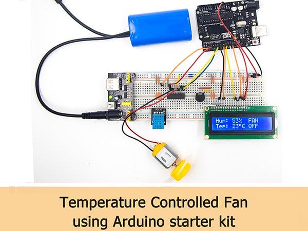
Use the Arduino kit in my hand to make a smart fan that automatically turns on or off and automatically adjusts to temperature.
In the experiment, I used Arduino UNO as the main control board, processed the data collected by the DHT11 temperature and humidity sensor and controlled the 1602 display. The 1602 display showed the current temperature and humidity and the fan working status.
PS: For the convenience of experiment, here I use a DC motor instead of a household fan, but the principle is the same. If you want to use it in a household fan, just add a relay control.
1.Function introduction- Temperature and humidity detection
- LCD display
- Automatically turn the fan on and off
- Automatic speed regulation according to temperature
In this experiment, Arduino mainly controls the motor by reading the value of DTH11.
When the ambient temperature is less than 26 °C, the fan is turned off and “FAN OFF” is displayed on the LCD.
When the ambient temperature is greater than 26 ° C and less than 28 ° C, the fan rotates at a low speed, and the LCD displays “FAN ON 1” (here, “1” means that the current fan speed is one gear).
When the ambient temperature is greater than 28 ° C and less than 30 ° C, the fan rotates at medium speed, and the LCD displays “FAN ON 2” (here “2” means the current fan speed is second gear).
When the ambient temperature is greater than 30 °C, the fan rotates at the fastest speed, and the LCD displays “FAN ON 3” (here, “3” means the current fan speed is the third gear).
Of course, this value can be modified, you only need to modify the temperature according to your living environment.
2.Things used in the Kit1、Arduino UNO
Working voltage: 5V
Input voltage: USB powered or external 7V~12V DC input
Output voltage: 5V DC output and 3.3V DC output and external power input
Microprocessor: ATmega328 (Chip data sheet is in the documentation)
Bootloader:Arduino Uno
Clock frequency: 16 MHz
Support USB interface protocol and power supply (without external power supply)
Support ISP download function
Digital I/O port: 14 (4 PWM output ports)
Analog input port: 6
DC Current I/O Port: 40mA
DC Current 3.3V Port: 50mA
Flash memory: 32 KB (ATmega328) (0.5 KB for bootloader)
SRAM :2 KB (ATmega328)
EEPROM:1 KB (ATmega328)
2、LCD 1602
Introduction to the pins of LCD1602:
VSS: A pin that connects to ground
VDD: A pin that connects to a +5V power supply
VO: A pin that adjust the contrast of LCD1602
RS: A register select pin that controls where in the LCD’s memory you are writing data to. You can select either the data register, which holds what goes on the screen, or an instruction register, which is where the LCD’s controller looks for instructions on what to do next.
R/W: A Read/Write pin that selects reading mode or writing mode
E: An enabling pin that, when supplied with low-level energy, causes the LDC module to execute relevant instructions.
D0-D7:Pins that read and write data
A and K: Pins that control the LED backlight
3、DHT11
DHT11 digital temperature and humidity sensor is a composite Sensor which contains a calibrated digital signal output of the temperature and humidity. The dedicated digital modules collection technology and the temperature and humidity sensing technology are applied to ensure that the product has high reliability and 92 / 223 excellent long-term stability. The sensor includes a resistive sense of wet components and a NTC temperature measurement devices, and connects with a high-performance 8-bit microcontroller. Applications: HVAC, dehumidifier, testing and inspection equipment, consumer goods, automotive, automatic control, data loggers, weather stations, home appliances, humidity regulator, medical and other humidity measurement and control.
Product parameters
Relative humidity:
Resolution: 16Bit
Repeatability: ±1% RH
Accuracy: At 25℃ ±5%RH
Interchangeability: fully interchangeable
Response time: 1 / e (63%) of 25℃ 6s
1m / s air 6s
Hysteresis: <± 0.3% RH
Long-term stability: <± 0.5% RH / yr in
Temperature:
Resolution: 16Bit
Repeatability: ±0.2℃
Range: At 25℃ ±2℃
Response time: 1 / e (63%) 10S
Electrical Characteristics
Power supply: DC 3.5~5.5V
Supply Current: measurement 0.3mA standby60μA
Sampling period: more than 2 seconds
Pin Description:
1. the VDD power supply 3.5~5.5V DC
2. DATA serial data, a single bus
3. NC, empty pin
4. GND ground, the negative power
4、Breadboard Power Supply
The small DC motor is likely to use more power than an UNO R3 board digital output can handle directly. If we tried to connect the motor straight to an UNO R3 board pin, there is a good chance that it could damage the UNO R3 board.
Product Specifications:
• Locking On/Off Switch
• LED Power Indicator
• Input voltage: 6.5-9v (DC) via 5.5mm x 2.1mm plug
• Output voltage: 3.3V/5v
• Maximum output current: 700 mA
• Independent control rail output. 0v, 3.3v, 5v to breadboard
• Output header pins for convenient external use
• Size: 2.1 in x 1.4 in
• USB device connector onboard to power external device
Setting up output voltage:
The left and right voltage output can be configured independently. To select the output voltage, move jumper to the corresponding pins. Note: power indicator LED and the breadboard power rails will not power on if both jumpers are in the “OFF” position.
Important
Make sure that you align the module correctly on the breadboard. The negative pin(-) on module lines up with the blue line(-) on breadboard and that the positive pin(+) lines up with the red line(+). Failure to do so could result in you accidently reversing the power to your project
5、L293D
This is a very useful chip. It can actually control two motors independently. We are just using half the chip in this lesson, most of the pins on the right hand side of the chip are for controlling a second motor.
Product Specifications:
• Featuring Unitrode L293 and L293D Products Now From Texas Instruments
• Wide Supply-Voltage Range: 4.5 V to 36 V
• Separate Input-Logic Supply
• Internal ESD Protection
• Thermal Shutdown
• High-Noise-Immunity Inputs
• Functionally Similar to SGS L293 and SGS L293D
• Output Current 1 A Per Channel (600 mA for L293D)
• Peak Output Current 2 A Per Channel (1.2 A for L293D)
• Output Clamp Diodes for Inductive T ransient Suppression (L293D)
To use this pinout:
The left hand side deals with the first motor, the right hand side deals with a second motor. Yes, you can run it with only one motor connected.
Arduino Connections:
M1 PWM - connect this to a PWM pin on the Arduino. They're labelled on the Uno, pin 5 is an example. Output any integer between 0 and 255, where 0 will be off, 128 is half speed and 255 is max speed.M1 direction 0/1 and M1 direction 1/0 - Connect these two to two digital Arduino pins. Output one pin as HIGH and the other pin as LOW, and the motor will spin in one direction.
Reverse the outputs to LOW and HIGH, and the motor will spin in the other direction.
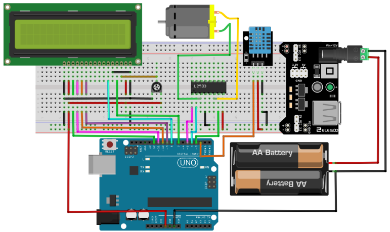
ConnectionSchematic:
Wiring diagram:
Step 1: Connect the modules together by wire according to the above schematic
Step 2: Open the IDE, load the attached program, and download the program to the Arduino board.


_mAvwvDvmh4.jpg?auto=compress%2Cformat&w=48&h=48&fit=fill&bg=ffffff)


Comments
Please log in or sign up to comment.