


Hardware components | ||||||
_ztBMuBhMHo.jpg?auto=compress%2Cformat&w=48&h=48&fit=fill&bg=ffffff) |
| × | 1 | |||
| × | 2 | ||||
| × | 2 | ||||
The finished project is a custom aftermarket valved exhaust controlled by a button inside the cabin powered by an Arduino Uno!
Purpose:An aftermarket exhaust with variable flaps was installed in a Hyundai Genesis Coupe that could only be actuated via a RF remote control. While cool, I love physical buttons, and the idea to have a button part of the car factory interior seemed like a fun challenge.
Thus, the project was to use an existing button location in the car to control the car's exhaust. An Arduino Uno handles the logic for this project, so that when the button is pressed the exhaust opens, and when pressed again, it closes.
Examining exhaust module:The first step involved examining the circuit for the stock FR unit. This is what receives the button press from the remote and actuates the exhaust valves.
The circuit is simple in that it involves two relays, one to open, and one to close the exhaust. I was able to create my circuit by manipulating these relays.
By completing the circuit on the coil side of the relay to ground I was able to manually activate each relay. The photo shows the wires added to the relay coil. This takes care of how to make the motors move, since the motors are controlled forward and backwards by these relays.
The next step involved the cars button module. In the US market the Genesis has a location for an additional button that was only intended for the European market. Therefor, in the US, the button was replaced with a non-movable blank button. Essentially, we have a button location that doesn't move but has the possibility, electrically, of having a button, since the same circuit board was used in both the US and EU market. The objective now is to make it move.
After removing the button blank, sanding free some of the plastic, and adding a 3D printed spacer, the button was now able to move freely.
While the button moves now, we still need to make it work electrically. After examination of the circuit, a surface mount button was added to the free solder pads intended for the EU button location. Two wires were also cut on the wiring harness to the board. These two wires will serve as the wires for reading our button state on the Arduino.
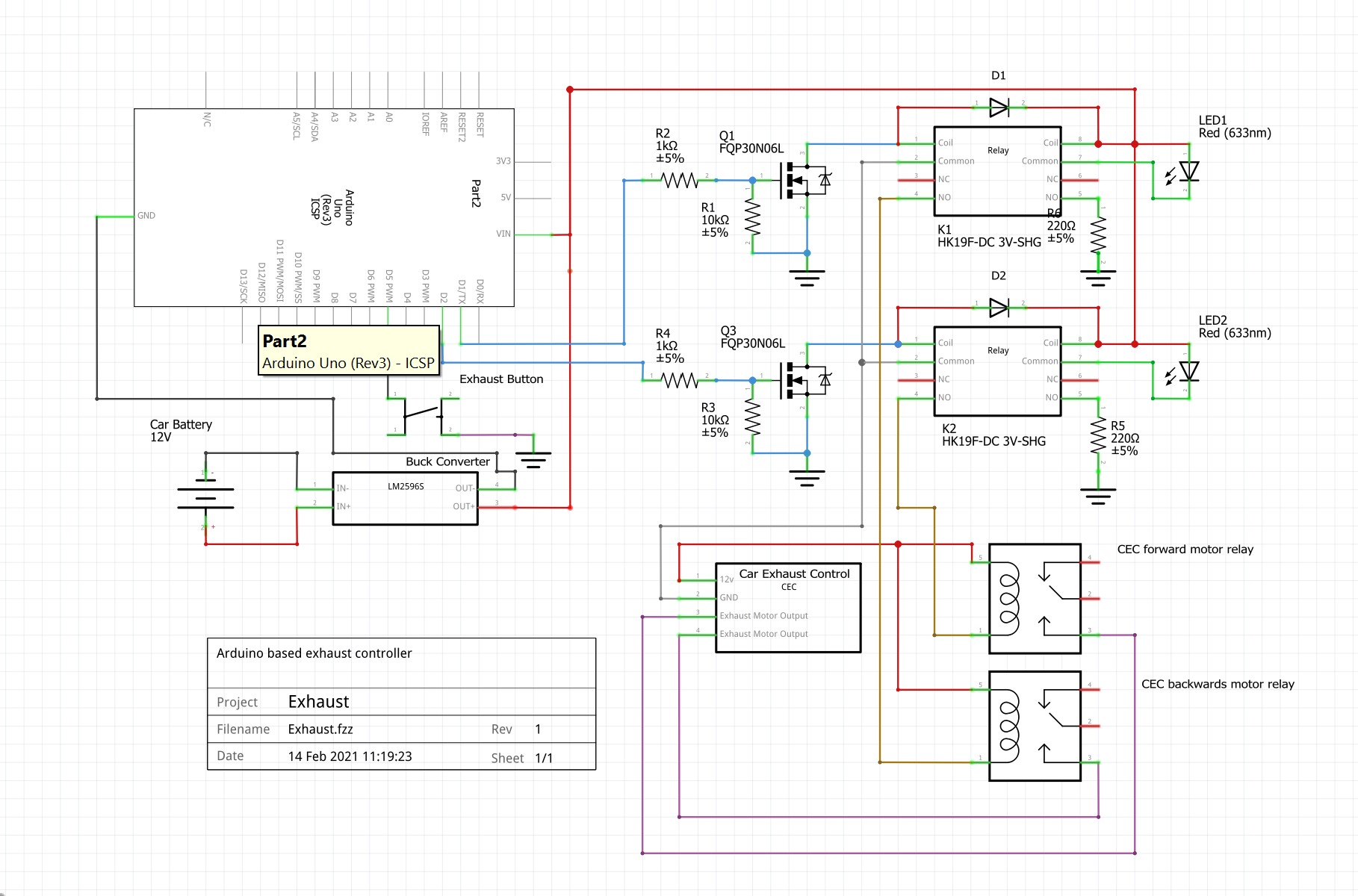
The main hardware for our project includes two relays and two mosfets. The Uno I/O pin will activate the gate of the mosfet which in turn will allow current to flow to the coil side of our added relay. When this relay is active it will complete the circuit that we modified on the exhaust module. Thus, our relay will complete the coil side circuit of the exhaust module, which in turn will active the exhaust module relay and active our exhaust flaps!
The code for our project is quite simple. Essentially we will read the button state of our new button and if a change is detected we will active our relays to open and close the exhaust.
Car mounting and wiring:First the Arduino module and wiring harness was made and connected to the original exhaust module. The Arduino module is protected by a 3D printed case, with power button and status lights.
Then the units where installed in the car. Finally the button was wired up to the Arduino, completing our circuit.
The finished projected is a custom aftermarket valve exhausted controlled by a button inside the cabin powered by an Arduino Uno.
This was a fun and satisfying project and adds a new level of enjoyment while using the exhaust system.
Happy coding all!


Comments
Please log in or sign up to comment.