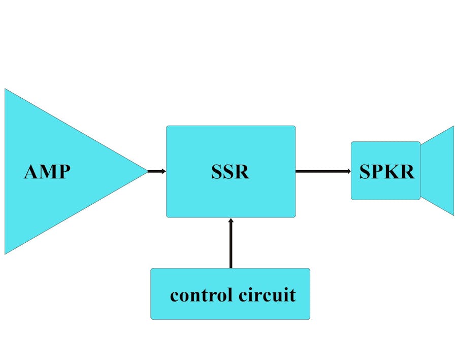
Intro
It is difficult to find cost effective mechanical relays that can be guaranteed to switch an amplifier output fault level current without catastrophic damage with 75 V rail and perhaps 30 or 40 A being a worst case scenario when a big amplifier has a short between its output and ground. When a big amplifier output stage fails short to either of its supply rails with a typical 4 Ohm speaker load, currents in the order of 20 A can be expected.
While conventional relays can be used, they have a small problem ... when a high power amplifier fails and the output goes DC, there could be 100V or more with a load impedance of perhaps 4 ohms or less. Breaking 100V at 25A DC is a very difficult job for a relay, because the DC allows a substantial arc to be created across the contacts. On the other hand MOSFET’s can switch fault level currents and voltages almost indefinitely when operated within the device ratings. Importantly, there is no wear out mechanism with MOSFET based Solid-State relays (SSRs). There are any number of SSRs available that are suitable for DC, but comparatively few low-distortion types that can handle the high AC voltages and currents that are typical of high power amplifiers. There are a many that can handle up to around 2.5A at voltages as high as 600V, but comparatively few that can handle the 30-40A or so that is needed for a high power amplifier driving low impedance loads.
How it works
600V CoolMOSª G7 Power Transistor (2 pcs) will be the core of SSR. My design also uses two photo-voltaic couplers in parallel to drive the mosfet gates, speeding up the switching time, and thus the dissipative energy handing capability of the SSLR during switching.
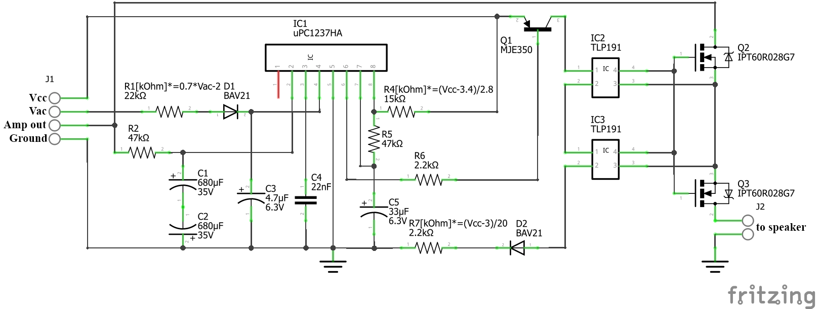
I am using IC uPC1237 for speaker protection in almost all my power amplifiers, because schematic is very easy to build with few external components.
When the amplifier is turned ON, the Speaker Protection Circuit is supplied with AC (from transformer secondary winding - Vac) and DC voltage (after diode bridge and smoothing capacitors - Vcc), and it starts to operate. The uPC1237 IC will monitor the output voltage of the amplifier applied to pin2. In the same time it monitors the voltage on pin 4 to detect if the AC is present to enable further operation steps. If the value of the DC component at the output of the amplifier is close to zero, and the AC detect is present, the capacitor connected to pin 7 will charge through resistor R5 connected to pin 8 (Vcc) and when the threshold value is reached the output pin 6 will toggle, allowing the amplifier to be connected to speakers. The value of C5 and R5 determines the delay time and the value of the R2 determines the maximum DC offset voltage allowable before the Speaker Protection Circuit will disconnect the speakers.
The choice of resistor R1, R4 and R7 values depends on the voltage of the power supply - Vac and Vcc. The formulas for their calculation are shown in the diagram.
All MOSFETs have a gate-source capacitance that must be charged and discharged when the MOSFET is switched on and off. Although this must be considered, it is still possible to get switching times in the order of a few milliseconds, and this will generally be considered acceptable. This design uses two photo-voltaic couplers (IC2 and IC3) in parallel to drive the MOSFET gates, speeding up the switching time, and thus the dissipative energy handing capability of the SSR during switching. Relay unit is presented in the diagram:
To turn on the Q2 and Q3 a voltage higher than the gate threshold voltage Vth of the transistor is needed. In our case the Vth is 4V (max). In the case of photo-voltaic couplers TLP191 we obain 7V, which is quite enough.
The scheme is shown for one channel. I plan to use it for a subwoofer. At this stage, I modeled the circuit by wire mounting, so the printed circuit board is not provided.


Comments
Please log in or sign up to comment.