


Hardware components | ||||||
 |
| × | 2 | |||
 |
| × | 3 | |||
| × | 5 | ||||
Software apps and online services | ||||||
 |
| |||||
| ||||||
Hand tools and fabrication machines | ||||||
 |
| |||||
| ||||||
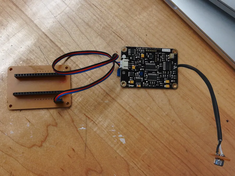
Sound Sensor
The first step was to figure out how to let the microphone on the sound sensor hear sounds without letting water touch it or the board. We came up with a few ideas, including encasing the whole sensor in tape, foam, or a mesh that wouldn't let in water. We eventually settled on removing the microphone from the board and soldering it to a wire, and then soldering that wire to the board. That way, we wouldn't have to worry as much about the board getting wet and only had to worry about protecting the microphone. We created a custom breakout board for the Photon to make it easier to connect the sensor to the correct pins on the Photon/Electron.
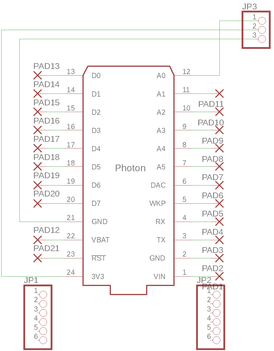
Photon/Electron Code
Next was to write the code. All we had to do was write the code to pull the data from the Photons and Electrons and put it into a Google Sheets. We had to find out how to pull published data from the Particle Cloud and format it correctly into Sheets.
Testing
To test the sensor, we placed it in a box with the microphone muffled by a sweater to prevent any outside noises from getting in. We placed a phone playing white noise in the box with the microphone so we could get control data.
Innovation Creation LabStage 1 - Questioning, Research, and ScoutingQuestions/Research
- Ways to make the nodes weatherproof
- Prevent water from coming in contact with electronics
- Limit the humidity/condensation inside of device
- Which materials and machines are best to use
- Practical ways to attach sensors to walls, poles, etc.
- Which microphone to use
- How to reduce the amount of echo within the enclosure
- Possible ways to remove the microphone from the breadboard
- What should be the size of the final design
- How would the electronics fit into the design
- Best weatherproof mesh to use
All would determine the overall shape of the sensor enclosure.
Scouting of possible attachment sites
- Visited the rooftop balcony of the Cubs’ office building
- Provided a sense of location and ideas for distributing the sensors around the area
- Took pictures of possible deployment areas
- Various parking lots around Wrigley
- Green and Brown lots
Sketching
Putting ideas on paper based on the categories and questions developed in the previous stage. The Sketches
- Drawing to scale and labelling components
- Accounting for weather conditions and outside factors to protect sensor
- Not going into specific details of how they are put together (screws and attachments) but working with the concepts and shapes that would work well
- Thinking about materials, space for electronics, and other unique features depending on what was being measured
- All the sketches are laid out for the group to look at them so the designs can be refined
- With new information, sketches become 3D models in Tinkercad
Tinkercad Models
- Tinkercad is a program used to create 3D models for use in 3D printing
- However we used the program in order to visualize and edit our original ideas shown in the sketches
- Given two weeks of editing with a checkpoint after one week
- Never intended to be the final product, but a way to find good designs that might not have stood out in sketching
- Having 3D designs makes it easier to build off of the template when moving into physical prototyping
- More consideration given to how the node would be put together and affixed to surfaces
Design Requirements
- Examples of the node types and certain things (perforated walls, etc.) which can benefit the electronics inside
- The node should be able to attach to different locations: poles and I-beams
- The node should be durable in different weather conditions
Materials Used. Inexpensive lo-fi prototyping - Using inexpensive materials to create replicas of the finished node
- Cardboard
- Hot Glue
- Exacto Knife
- Tape
- String
- Ruler
- Pens
Process
- Cut the cardboard into desired shapes
- Glue cardboard together
- Keep in mind the required aspects of the node type (wire placement, water direction, etc.)
- Presentation
- Shared thoughts on prototypes with class
- Explained the advantages + discussed the disadvantages of each potential node
- Discuss alternatives to certain design choices and prep for the next phase
- Talking Points
- This is a mid step between conceptualization and creation of the actual node
- Prototyping is important because it allows you to envision what you want to create without spending too much money.
- Use of the right measurements is key as it gives a clear visualization of what the node will look like
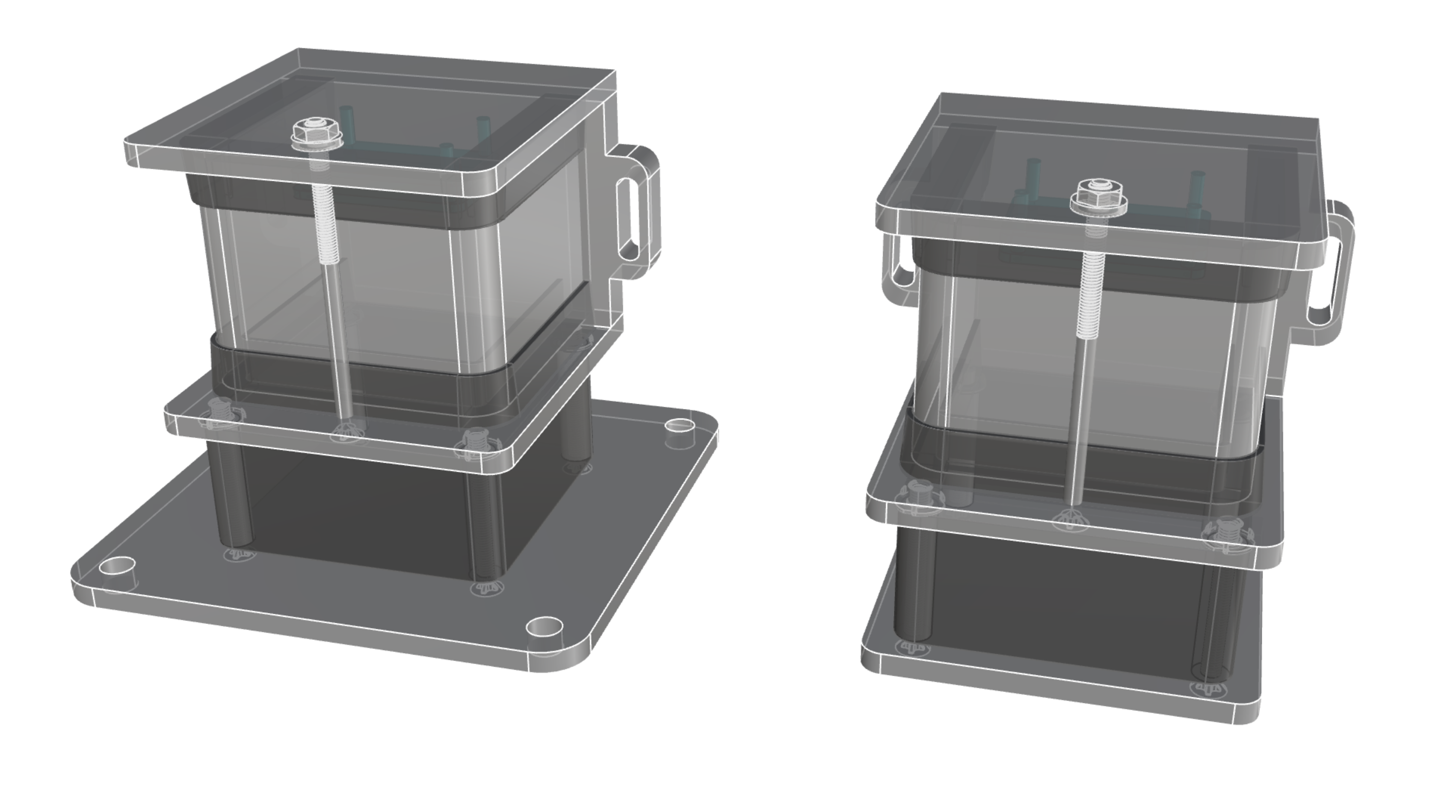
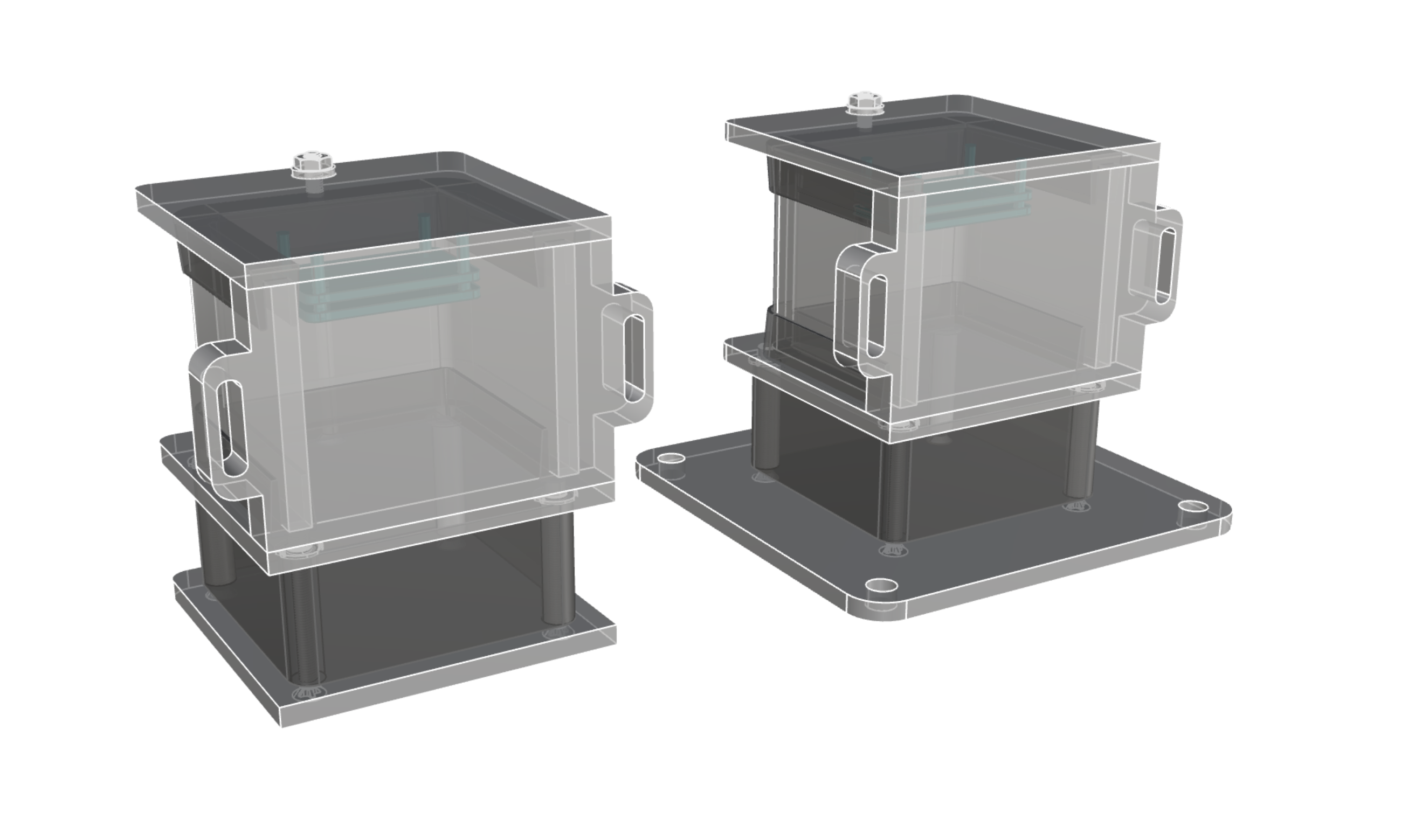
The 3D models that came from prototypes
Parts
1. 3 Plates
- Carve out the pieces
2. Acrylic front
- Laser cut piece
- Bend piece to appropriate shape
3. Rubber gasket
- Cut to appropriate size of the acrylic
4. Bottom netting
- Cut to appropriate length and size of bottom half of the node
Assembly:
- 1) Use mallet to knock T-nuts into the bottom of the middle plate. It has a hole in the center and 4 holes in the corners that don't go all the way through the material. The t-nuts go in these 4 holes.
- 2) Countersink the 4 holes in the corner of the bottom plate (has 4 holes in the corners that go through the material completely). We don't have a countersink bit that matches the angle of the machine screws so use a slightly larger one and be careful not to go all the way through the material.
- 3) Clamp the middle plate (with the t-nuts mounted) to the backplate (with channels and "ear") and use the guide holes in the bottom of the middle plate to pilot two holes into the side of the backplate. Flip the backplate around and do the same on the other edge. Use panhead screws to attach these two plates together with a strip of foam between them. Trim excess foam.
- 4) Use a drill bit to expand the size of the hole in the center of the middle plate. Microphone board goes here with mic facing downwards.
- 5) Use belt sander to modify the edges of the c-shaped acrylic pieces to fit into the assembly tightly with gaskets. Drill a hole in the front center of the middle plate and top plate for a 10-32 screw at the front edge of the gaskets of the top and bottom of the c-section at the front.
- 6) Assemble baseplate and middle plate by using 4 2" screws through the bottom plate, with long spacers, into the t-nuts.
- 7) Mount sound boards into top plate using 4-40 screws and spacers. Should be centered left-right and towards the backplate (at least.75" away from the back edge of the top plate). The c-sections are not all the same size/depth so make sure it fits per device.
- 8) Hot glue the microphone board in place in the middle plate, inside the box. Then place the antenna diagonally in place above it within the c-section place. Finally seat the top plate and attach it with 2 pan head screws. Use foam strips between the backplate and top plate and trim excess.
- 9) Pass the long 3" screw through the two holes you drilled previously in the top and middle plates and fasten with a bolt, tightening to compress the gaskets on the top and bottom of the c-section.
- 10) Wrap the spacers between the bottom and middle plate with double-sided tape. Wrap the hdpe mesh around the spacers, starting and ending with a little extra at one corner. Use wire to loop around the spacer where they meet and tighten to hold fabric in place.


Comments
Please log in or sign up to comment.