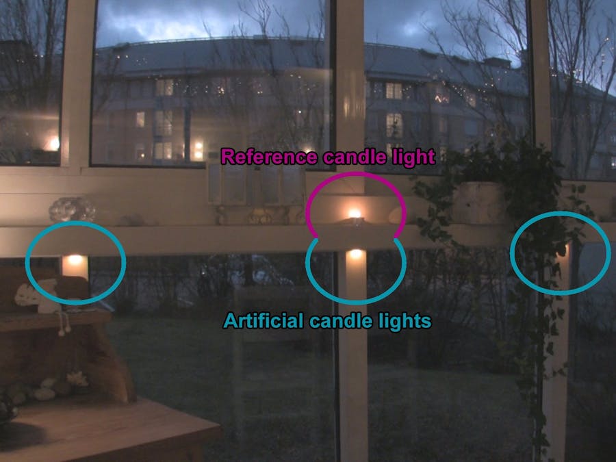
A while ago I started working on a project to subtly light up our atrium room which gets a bit too gloomy during the autumn and winter time. I wanted something more natural looking than hard LED lights, preferably the live look of flickering candles.
For the impatient people (who don't want to scroll all the way down to find a video), this is the result:
...and a Christmas version:
Now, back to the story:
But creating a realistic artificial flame is not an easy task, so my idea was to place the lights in a way where you don't see the "flame" directly, but merely the light it produces, dancing on the wall.
Since the room is mostly made of glass walls, the obvious choice was to let the light be projected on the white beams holding the windows. I decided to place the lights on the bottom of the horizontal beam, projecting the light downwards on the vertical beams.
Since I wanted to be able to control each "candle" individually, the choice of LED light was easy; it should obviously be a set of WS2812-based LED modules, so I ordered 100 individual LEDs.
As you can see in the picture above each LED has six connections – and a direction marked with an arrow on the backside.
Two of the connections are marked 5V, two are GND and then there is the Din (Data In) and the Dout (Data out). The two 5V are connected and so are the two GNDs. So in practice there are four connections; 5V, GND, Din and Dout.
After some experimenting with different number of LEDs per "candle" I came up with a number of four. This number allowed me to make enough interesting light manipulations on each beam to make a realistic candle look without demanding too many LEDs.
However, should I have to do it again, I would have ordered a set of 2-by-2-LED modules, to simplify the assembly.
The controller didn't need to be very advanced, and my assumption was that an Arduino Nano would suffice.
The placement of the Arduino wasn't obvious. In the end I chose to put it on the horizontal beam itself, behind the thick pillar that is visible in the first photo above (far to the left). The pillar is placed in the corner of the room where the two glass walls meets (of which the "right" wall is shown in the photo). This way I could have the LEDs on two parallel strings – one for each wall – to minimize the physical length of each string. Now the total length of each string would be around 4 meters (13 ft) instead of having one twice of that.
The Adafruit NeoPixel Überguide was a really good read here; if you plan to play with WS2812 LED modules you should definitely read it through! For instance, it told me why it's good to limit the physical lengths of the wires.
Hiding cables......wasn't that hard in my case since the LEDs were to be placed on the bottom side of the horizontal beam. I looked around for a cheap cable channel and found one on IKEA (can't tell whether it's ironic or obvious, being from Sweden).
The LED modules themselves were simply placed with a strong double sided sticky tape.
Creating the LED modulesSince I didn't want to solder the whole thing together on a single full-length string (I imagined the cable jam I would encounter trying to install the thing on the bottom side of the beam) I decided to build the LED modules with connectors for the cables.
The LED modules were to be placed just next to the vertical beams in order to get as much light as possible be reflected upon it. I also wanted to have the cable going close to the beam – and I needed to honor the direction of the LEDs. This led (no pun intended) me to have two versions of the module; one setup placed on the string going to the right from the Arduino and one going left.
The two module versions required two unique soldering layout, where the main difference was keeping the data flow going from the correct LED to the next.
Since the LEDs are pretty small, about 9 millimeters in diameter (3/8"), it wasn't easy to solder them; and given my lack of soldering experience the result isn't that nice and pretty. But it worked.
The solderingBefore soldering, I cut off a 2-by-2 LED module from the 2-by-5 original sections. Then I painted one end red and the other one black to mark the sides close to the 5V and GND (in order to prevent stupid mistakes).
Step 1 The first soldering exercise was to put a 'drop' of solder on the tiny metal island on each LED.
The next step was to connect the simple straight, close-by connections.
Then following cables needed to keep their insulation, since they were going over each other.
All in all there were five beams in each direction – plus the corner beam – giving a grand total of eleven beams. Since each LED module had four LED, the number of individual LEDS are 44.
After a few modules I got the hang of it, and in the end I could solder a complete module in about 30 minutes.
The "short-cable-trick"Many of the tiny cables needed their insulation, but it was hard to cut of just enough insulation on each end to expose the inner core when the total length of the cable was less than a centimeter.
Then I figured out this (obvious) trick:
1. Solder one end of the cable, then bend and cut it to the desired length. (In this example the non-soldered end should be connected to the Dout of the lower right LED in the picture below.)
2. Slide down the insulation a bit.
3. Cut off the desired length from the freed insulation.
4. Slide the insulation back, exposing the core on the free end. Tadaa!
This way the exact length of exposed cable core could be created, and the result was pretty nice:
In the end the LED modules should be attached up-side-down on the beam, so the soldered, cable-filled back-side must be prepared to hold the sticky tape.
I came to use some random flat plastic that I simply cut into squares. These were simply attached to the LED modules with hot glue.
Here are all the complete modules! Hooray!
(At this point it was vital to have some marking on them, to separate the ones going left from the ones going right!)
The complete modules was easily attached using strong sticky tape on their now flat backsides.
Making the cablesLuckily I had a roll of old telephone extension cord laying around. This cable had four separate wires which was more than enough, since I needed three wires (5V, GND and data).
Mounting the female sockets without the special crimping tool wasn't that easy, but totally doable.
The cable channel was easily mounted; just cut it up into suitable lengths and use the pre-attached sticky tape to attach it to the horizontal beam.
This is what a finalized mounted module looked like:
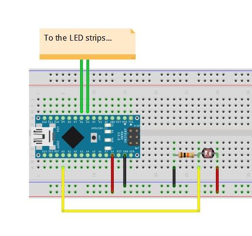
Since I don't want to turn on the lights manually when it gets dark and turn it off afterwards, I put in a photo resistor.
I didn't want a simple on/off, but a gradually change of light intensity during the twilight time. For this reason I needed to know the analog value of my photo resistor at the point in the evening when I decided that "daylight" turned into "twilight" and the point when "twilight" turned into "darkness".
In the graph below the red curve represent the analog reading from the photo resistor as it shifts during a day (not an actual reading below, just my free-hand drawing). The two faint horizontal lines marks the two levels; the top one is the limit where "daylight" turns to "twilight" and the bottom one where "twilight" turns to "darkness". So, when the red curve is above the top horizontal line I consider it to be DAY, and when it is below the bottom one it is NIGHT.
The green straighter line is the the "cleaned" daylight measurement, i.e. minimum (0.0) during night time and maximum (1.0) during the day, and a linear slope during twilight.
To know the actual analog readings I hooked up four photo resistors to an Arduino together with an LCD screen to show the current, minimum and maximum values of the four resistors. I used four because I didn't know if I had a bad one, so if most of them would have approximately the same reading I knew they would be working. Obviously I placed the device in the same spot where I intended to have the Arduino driving the LEDs in the end. This is how it looked:
Since the LCD is quite limited I showed the reading of one photo resistor at the time for about five seconds. Then during the day I went over from time to time and wrote down the numbers on a piece of paper. (Obviously I could have kept it hooked up to my laptop and had the numbers be sent on the serial connection, but I needed my laptop during the day and didn't want to sit in the atrium the whole day).
In the end I decided that it is dark below "630" and light above "800". But those numbers obviously just fit my photo resistor together with the 10 kΩ resister I used in series, so it's not an absolute truth.
The Arduino Source CodeI wanted to be able to have different types of lighting effects, not only candle lights. For this reason I built the source code modular, trying to isolate the different mechanisms in different files for easier overview.
The main .ino-file is kept really small. I basically just starts up the whole thing and calls Update() on a couple of helper-classes (which in turns does the trick).
Currently the source code has support for two different effects; the candle light effect and a "Christmas" effect. At the moment the choice of effect is hard-coded which means that I need to recompile the code if I want to make a switch. In the end this should be controlled using a remote control -- or, even better, a smart phone. We'll see.


_3u05Tpwasz.png?auto=compress%2Cformat&w=40&h=40&fit=fillmax&bg=fff&dpr=2)
Comments