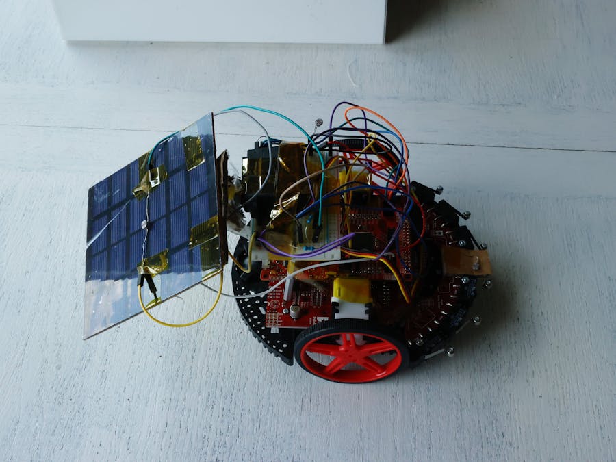
This small solar follower is the start of multiple iterations of a design I hope to implement before my college career is over. As I initially started this project under the TI University Summer Program, I aimed to keep the scope of it small, and doable within 1 month.
The first thing I wanted my solar follower to do was to initially cycle through every reasonable angle, and find the brightest possible angle to start tracking the sun at. This ensures that whenever the robot is booted up, it can start harvesting energy at its maximum capabilities. This was achieved by reading the value of a resistor attached to the solar panel, as the servo rotates. This is called FindInitialPos() in my code.
Next, I wanted to make sure that the robot would take into account the weather of the day. To do this, I implemented a function that would read in the values from a photoresistor attached to the solar panel as the servo rotates, store the maximum, and compare them to the values I provided (found through experimentation). This is called FindMode() in my code.
While the day goes on, the sun's position changes. To account for this, I created a function that compared the weather value found from the FindMode() function, and comparing it to the current value the photoresistor is reading. If it finds that it is dimmer than the the weather it initially finds, the robot assumes that the sun has moved, and the servo moves to find the next angle that provides sufficient brightness. This is called OptimalAngle() in my code. A way to improve this function would be to compare the brightness values of servo angles to see if the next servo angle was brighter or dimmer, and continue until it finds no angle brighter. For example, if servo angle X has a brightness reading of 800, and servo angle X+1 had a brightness reading of 801, the servo would then assume X+1 is the brightest angle and check X+2 to ensure this was true. This would confirm that the angle truly is the optimal angle, and not just a sufficient one that is provided in this current function.
Finally, I implemented a function that would attempt to avoid shaded areas, to ensure maximum production from the robot. This was done by attaching a photoresistor on the front of the robot, and one towards the back. Then, I simply read in values continuously, and if there was a wide enough gap in the brightness, the robot would assume there was shade in the dimmer direction, and drive the other way. Unfortunately, I did not factor the size of the solar panel when designing the robot. This made it impossible to put the photoresistor on the very back of the robot, as it would always be shaded by the solar panel. With more time I would create a small platform to put on the back of the robot, rather than settle for putting the current photoresistor on the middle of the robot.
Building the physical robot was somewhat difficult, as I had little access to power tools and other materials. Because of this, I built everything with cardboard and tape. As flimsy as this sounds, the final robot ended up working much better than I expected, and turned out surprisingly sturdy. In later implementations I expect to use Lexan sheets to create the platforms, and to print 3D housings to house other components.
Other future improvements include building a voltage limiter, and figuring out a way to hook up the solar panels to the power supply of the robot. As it is right now, the solar panel can only charge an external battery hooked up to the FuelTank BoosterPack.
A video is included to more easily see my project and what I have described. I hope you enjoy!


Comments
Please log in or sign up to comment.