This was my 2016 Halloween quick project. I found myself with about 45 minutes to come up with a costume and some fun add-on. I ended up grabbing an old vampire set I had and made this beating heart to put underneath.
The animation in the main image shows the beating heart assembled underneath the black fabric of the costume.
PlanningThis project is based on an Arduino-compatible Adafruit Flora, their larger wearable platform. It can be done with pretty much any small Arduino board, but the form-factor of the Flora and the number of IOs available makes it a perfect platform. It also has a connector for a battery, so this project can be built without external power-related components.
For the beating heart itself, the Adafruit 8x8 Neopixel Matrix is an ideal (if somewhat expensive) base. It is easy to control it with a single data wire and pixel color is controllable. It can also be powered directly from a 1-cell LiIon battery, and works "well enough" (for a quickie) driven by the Flora's 3.3V signal pads. Note: I used an older Flora v1 for the project. The newer versions will work just as well.
Portable power is provided by a single cell Lithium Ion Polymer battery. The one I used is a 1200mAh, which is of a nice size for this type of wearable, but other sizes can be used. If using a smaller battery, make sure that the discharge rate can be accommodated and that the capacity is sufficient for the application.
Rounding up the electronic components are two 10k trimmer potentiometers. These are used to tune the color of the heart and the beating frequency. They can be mounted directly on the Flora with no extra support or wiring and are a good match for wearables (small and easy to use).
If this is to be worn on the chest like my original project, elastic bands can be used to keep the bundle together and a chest strap (I used the strap from an old heart rate monitor) can hold the whole bundle in place without needing modify the clothing.
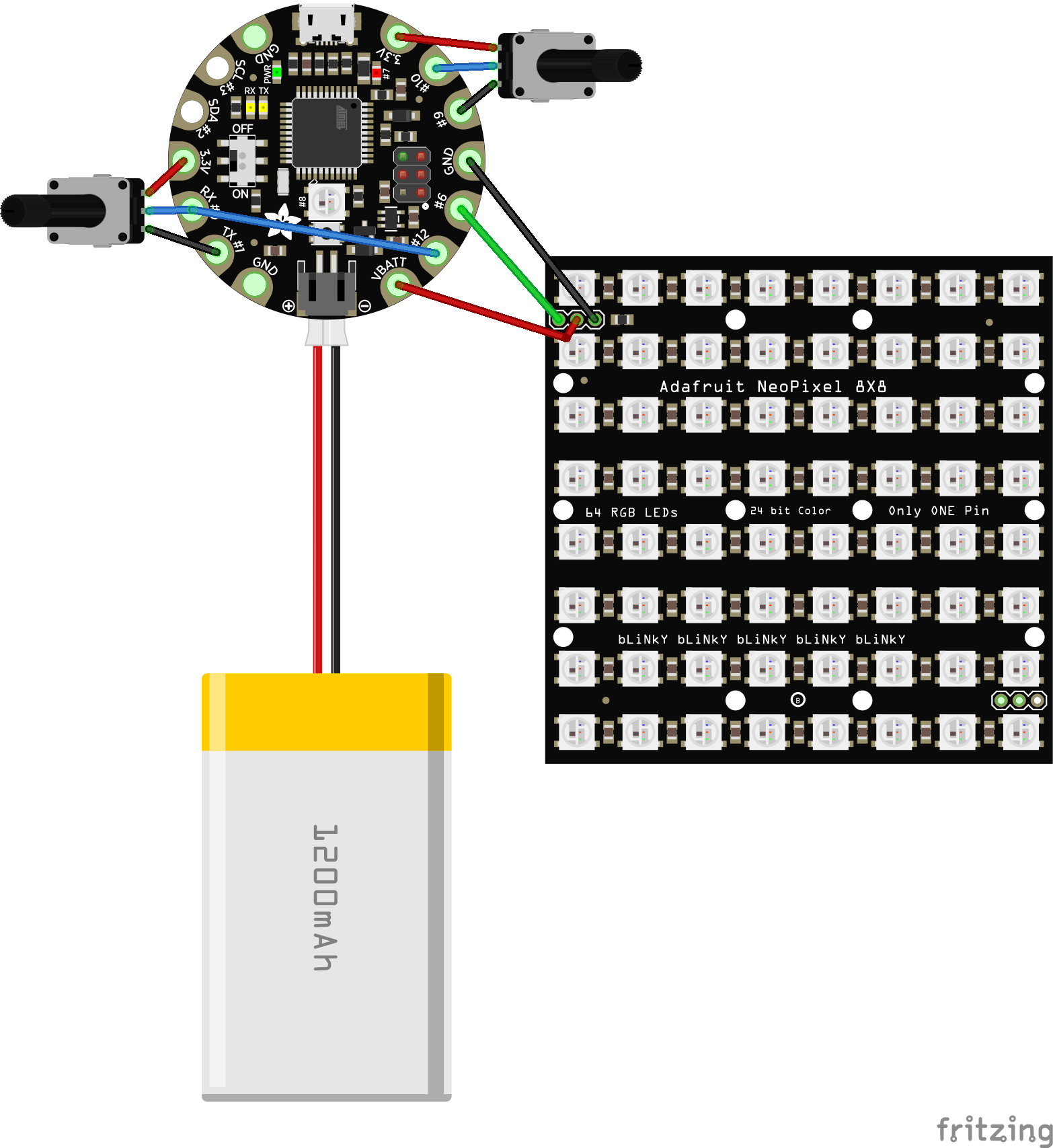
The assembly requires 14 joints to be soldered as shown on the fritzing diagram at the bottom of the page.
The first step is to mount the trimmers on the Flora.
Tip: Trimmers can be directly mounted on most Arduino boards and provide one or two inputs to easily select or tune parameters.
This is one of my favorite tricks and I use it on most projects. Trimmers are potentiometers in a small form factor that are meant to be set once. For this use, the 2 outside legs of the trimmer are connected to GND and VDD (3.3V for Flora) and the middle leg to an ADC input of the Flora. As the trimmer control moves from end to end, the voltage of the middle pin varies from GND (0V) to VDD (3.3V) and the Arduino code can read the ADC and get a continuous (0-1023) value. This is much simpler than a multi-pin selector or a rotary encoder and can be used for continuous values (speed, color...) or selection (modes...) by using zones.
Tip: For low currents, a signal pin can be used as a GND or VDD.
This is a trick that works well for trimmers, as this makes it easy to find adjacent pins to mount them directly and the high resistance (typically 10k) guarantees low current needs (<1mA), which can be easily sourced by signal pins.
For this projects, two trimmers are used to tune the beating frequency and the color of the heart. The resistance value used in this project is 10k, but other common values can be used like 5k or 100k.
The first trimmer uses pin D10 (A10) for its signal input, 3.3V and D9 used as GND. Because of the natural location of the wires needed for the Neopixels, I decided to put the second trimmer on the oppose side. However, there is no analog pin on that side, so even though the second trimmer's signal pin is connected to RX, a wire connects RX to D12 (A11) under the board. The second trimmer uses 3.3V and TX as GND.
The Neopixel matrix connects to the Flora through 3 wires.
Power is provided by GND and VBATT. The Neopixels are natively 5V but run well down to about 3.5V. The VBATT pin is ideal for this as it is unregulated (so the power hungry Neopixels can get as much power as the battery or USB can provide) and it voltage level is 5V (USB) or 3.5-4.2V (battery).
The signal is provided by D6, a regular IO pin. This is not normally recommended as the Flora micro-controller is 3.3V, and that level is technically too low to reliably drive the Neopixel data pin (especially when on USB/5V). In practice, this is sufficient for this project, although there may be glitches visible when on USB/5V.
The Flora connects to the GND/PWR/IN pins of the matrix. The OUT pin is not used (it would be for chaining more Neopixels).
ProgrammingThe program shown at the end of this page is straightforward.
The pins are set up as needed (including the 2 signal pins used as GND). The main loop spends a few iterations increasing brightness, then decreasing brightness (asymmetrically to give a better beating impression).
The 2 trimmer/ADC inputs are used to pick a color (using Adafruit's ColorWheel example) and to tune the delay between brightness changes, which directly translates into the beating frequency.
MountingThe simplest mounting uses a chest strap and two rubber bands to fold the project around the chest strap as illustrated below.
The chest strap can then be put on the chest and a layer of closing put on top. The image below shows the resulting heart showing underneath the black fabric of a vampire costume.


Comments
Please log in or sign up to comment.