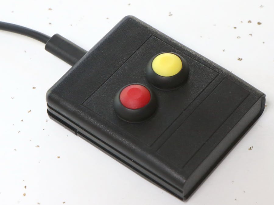
This is a very simple, yet useful introductory project to Arduino, USB and buttons. I use this project at work all the time. It saves me from having to reach for the keyboard or remembering keyboard shortcuts.
PlanningThe key component for this project is the Adafruit Trinket M0. It can be replaced by pretty much any of the other Atmel ATSAMD21-based boards like the Arduino MKR ZERO or the SparkFun SAMD21 Mini Breakout.
I like the Trinket M0 because it is really small (and this project only needs a small number of I/Os, so no need for the bigger boards) and it is inexpensive ($8.95).
I had originally made this project with the older Adafruit Trinket 5V using the Adafruit Trinket USB Keyboard instructions. This worked, but not completely reliably, especially behind some USB hubs. The original Trinket is ATtiny85-based and that chip does not have native USB keyboard capable hardware, so the project uses a bit-banged (i.e. software) implementation of USB. The SAMD21 inside the new Trinket M0 has USB keyboard and mouse capability in hardware and it has shown to be perfectly reliable.
There is a wide choice of enclosures and buttons to do this project. I just went to my local electronic store and bought some I liked. I added the references in the hardware list, but these are by no means the only or best options. Here are some parameters worth considering when picking an enclosure and buttons:
- Buttons should attach to the enclosure. Do not buy buttons that need to be soldered to a board.
- Plan for the mounting of the Trinket. The Trinket must be very solidly mounted to the enclosure to sustain the high stress of USB cable insertion. The enclosure will need to have a hole cut to insert the USB plug.
Tip: I recommend using solid core wires for this project as they are easier to solder and work with and they will not be exposed to repeated flexing.
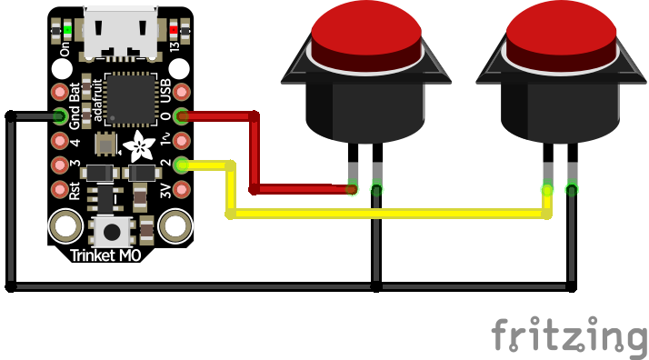
SolderingThere are just 7 solder joints to make on this project. The connections are shown on the fritzing diagram at the bottom of this page.
I suggest soldering the wires to the Trinket from the top (as shown on the picture below) so that there is no clearance issue at the bottom.
Most buttons have small holes in their legs. That makes it easier to attach the wires to the legs and greatly simplifies soldering.
If you use buttons as shown in this project that are screwed from the bottom, make sure you solder the buttons after they are in place in their respective holes.
Tip: Always test the code and wiring before starting to put the electronics inside the enclosure. Depending on the buttons used, this can mean that either the buttons have to be tested unsoldered, or they have to be desoldered and resoldered after installation inside the case.
ProgrammingIf you don't already have an Arduino environment installed, this is the time to do it.
Tip: If you plan on using a non-Arduino-branded board (like the Adafruit Trinket M0 in this project), it is easier to follow the manufacturer's instructions, for example the Adafruit Arduino IDE setup page, as they include setting up the environment with the corresponding boards and libraries.
Once the environment is installed, start a new project, copy the code at the end of this page, select the board type, the port and upload the program.
The program is set up to provide two keyboard shortcuts in response to a button-press: Windows-F4 and Windows-L. The first one toggles the mute button on Skype while the second one locks the screen on Windows. Any sequence of keys can be entered. See the Arduino documentation for more information on the key modifiers.
Tip: For key combinations, each key must be "pressed" by the Arduino code in sequence using a Keyboard.press() command for each key as shown on the example code.
EnclosureThis is the inside of my finished project:
To make the button holes, I used a body reamer (see hardware list). These are meant to make holes in RC car lexan bodies, but they work for most plastics. There are other types of reamers (e.g. luthier's reamers) that can also be used for this application. It is easy to make good quality, round, properly aligned holes, with a reamer.
To attach the Trinket to the enclosure, I layered and glued multiple layers of hard plastic and screwed metal screws through those. Since the front holes on the Trinket M0 are near several components, I used plastic washers to provide electrical insulation.
This particular enclosure had some internal structure to carry batteries, which had to be cut. finding the enclosure and modifying it for the project was by far the most time-consuming part of this build!
3D-printed enclosureA few months after having finished this project, I acquired a 3D printer and used this project as my first attempt at building a 3D-printed enclosure.
The result is somewhat smaller than the off-the-shelf enclosure:
The content is the same:
The enclosure uses three M3x10mm FHCS (flat head) hex screws and four 3/8 in. self-adhesive vinyl surface pads.
The enclosure was designed using Autodesk Fusion 360 as shown below:
The 3D-printable enclosure is posted on Thingiverse.


Comments
Please log in or sign up to comment.