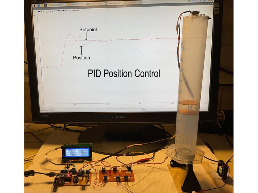
The PID Position Control of a levitating balsa disc assembly inside a 500ml graduated cylinder is a system designed for educational purposes . It complements the PID Temperature Control of a Miniature Thermal Chamber project found on Hackster.io at $ https://www.hackster.io/lenfromtoronto/pid-temperature-control-of-a-miniature-thermal-chamber-f48e73 in that it is a relatively fast responding process control system with very different process dynamics compared to the PID Temperature Control system. These differences will require very different PID tuning constants.
The system could be used as an inexpensive process control lab with many useful educational outcomes such as developing an understanding of process control and the effects of process dynamics on selecting the optimum PID (proportional, integral, and derivative) tuning constants. The lab would be suitable for students in electrical/electronics, mechanical, or chemical engineering / engineering technology.
The electronics for the PID Position Control System project and the PID Temperature Control of a Miniature Thermal Chamber project is the same . The IDE is the Arduino IDE and the serial plotter is used for both. Only the C code will differ.
The system hardware consists of a 500 ml plastic graduated cylinder with the bottom reamed out, a control board and an interface board , two 12 V DC fans , and an ultrasonic sensor . The balsa disc assembly is easily constructed using 4 pins and 2 45 mm discs cut using an exacto knife.
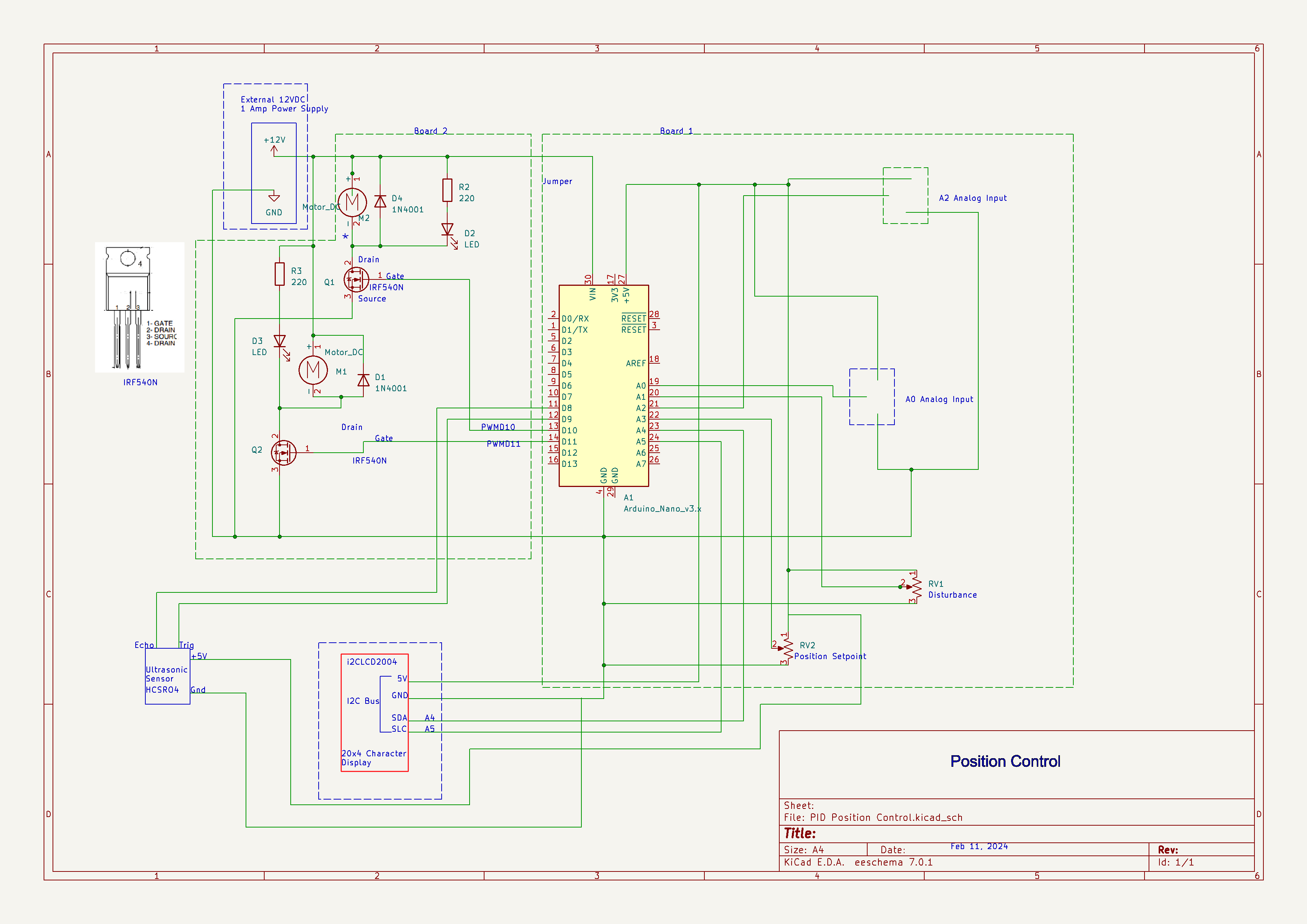
The control board consists of an Arduino Nano , a setpoint potentiometer for setting desire position in cm and a disturbance potentiometer that adjusts the disturbance fan.. The outputs from the Nano are 2 pulse width modulated signals that produce a variable DC voltage that drives the 2 fans.
The interface board utilizes 2 N Channel power Mosfets and uses the PWM signals from the Nano to produce a PWM output with a maximum voltage of 12VDC to supply the ther2 fans.
The following is a block diagram of the system:
The Arduino Serial Plotter is used to display the Position, Position Setpoint and the Disturbance. The following are the commands that are set from the Arduino IDE Serial Plotter:
- PB+ Doubles the current Proportional Band (decreasing the gain).
- PB- Halves the current Proportional Band (increasing the gain)
- Ti+ Doubles the current Integral Time
- Ti- Halves the current Integral Time
- Td+ Increases the Derivative Time by 0.1 sec
- Td- Decreases the Derivative Time by 0.1 sec
- enDist Enables the Disturbance Fan to turn on and off in a square wave manner
- disDist Disables the On/Off Square wave action of the Disturbance Fan turning it Off
The video describes the features and operation of the system.
Graduated Cylinder and Balsa Disc Assembly- Standard 500 ml plastic graduated cylinder
- 2 45mm balsa discs
- Discs are cut using an exactor knife, pinned and glued together
- Standard (sometimes called Mixed) algorithm
- Most commonly used in industry
- Reverse Acting
Runs independently with LCD display or along with Arduino Serial Plotter
LCD- Position Cm
- Setpoint cm
- Proportional Band
- Integral Time
- Derivative Time
- Proportional Component in %
- Integral Component in %
- Derivative Component in %
- Controller output - total of three PID components in %
- Connects to LCD Display via I2C bus
- Generates 2 PWM outputs to Power Mosfet Interface board
- C Code generated from Arduino IDE
- Setpoint and disturbance generated from 2 potentiometers connected to Nano analog inputs
- Ultrasonic Sensor calibrated 0 to 27 cm
- Power Mosfets IRF540N are switched at 490 Hz and operate via Pulse Width Modulation to vary the voltage on the 2 fans
- Red LED intensity varies with Voltage supplied to the fan
- Yellow LED intensity varies with Voltage supplied to the fan
Before the use of microcontrollers and computers PID controllers were implemented with analog electronic devices, the principle one being the operational amplifier.
Implementing PID control digitally uses an algorithm. There are several versions of the PID controller. The one implemented in this project is sometimes referred to as the Mixed or Standard implementation.
The mathematics of the PID mixed PID controller can be represented as the following.
Where:
Kc is the controller gain, Ti is the integral time, Td is the derivative time, and e is the error. Sometimes controller gain is represented as Kc = 100%/PB where PB is referred to as Proportional Band . A smaller PB then results in a larger gain.
The following is pseudo code for implementing the PID algorithm. It is not in the form of an actual programming language but more in the form of a flow diagram.


_3u05Tpwasz.png?auto=compress%2Cformat&w=40&h=40&fit=fillmax&bg=fff&dpr=2)
Comments
Please log in or sign up to comment.