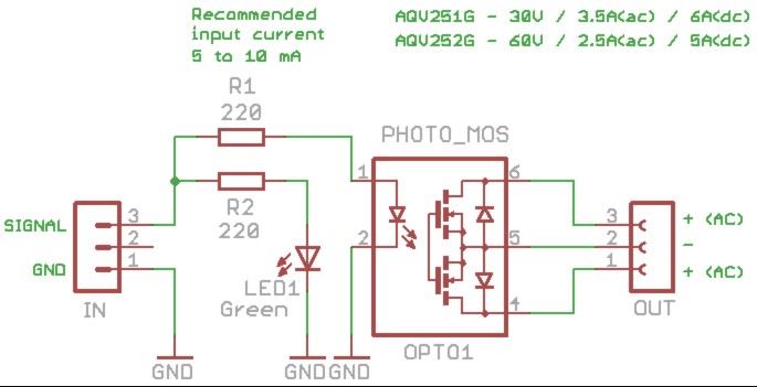
This is very similar to a normal relay, but it has features that I didn't even dream of on mechanical relays. It can switch in a millisecond, lasts virtually endlessly, requires only 5 Milli Ampere of pilotage, has exceptional insulation and is very small. Also the spare PhotoMOS can be easily replaced on the base, even with different patterns and possibly even with the cheap PhotoTRIAC to use for application in AC.
The input connector is a 3-pole, so follow the standard Thereminico which provides + 5VDC central pole. But in this circuit the +5 Volt is not used, then you can use two single cables Dupont for signal and to GND.
If you have to drive multiple forms together, you could combine the Central Server with GND, with a spot of solder on the bottom of the print. That way you could carry only one bulk cable (GND) and then use the Central Server to bring mass to neighboring modules.
This project is lucky. It concerns the Chinese for automating the screw-setting machines they use in production, and takes precedence over many others. It will be produced in record time and will soon be available at thereminostore.
Why use PhotoMOS instead of mechanical relays?Mechanical relays cost ten times less and bearing currents and voltages above, but they last 200,000 operations. This might seem too many, but doing the math you may be surprised. For example, we're designing a car wrench and there are two relays that switch twice every six seconds. If the production machine is functioning 24 hours a day, how long will the relay last? Maybe a few years? Wrong, each week will be both faults. Since then, the production machines are five, and soon to be ten, probably every day there would be one or two under repair. That's why, in some cases, you can't use the mechanical relays.
Why not simply use a Mosfet or Darlington?In this same page, some current projects show even greater bearing adapters and cost less. In some cases you may use them, but only a photo-MOS can give complete safety, to completely isolate the logic, from electrical disturbances caused by heavy loads, especially if inductive loads.
Types of connectionsDepending on the connection, you get a relay for AC or DC. With the connection “C”, usable only in “DC”, you get a doubling of the maximum current.
Characteristics of PhotoMOS- AcronymTensionmaximumCorrente_ACAOR.
- “A”Corrente_DCAOR.
- “B”Corrente_DCAOR.
- “C”Cost(aprox.)
- AQV251G30 Volts3.5 Ampere4.0 Ampere6.0 Ampere6
- EuroAQV252G60 Volts2.5 Ampere3.5 Ampere5.0 Ampere5
- EuroPVN012APBF20 Volts4.0 Ampere4.5 Ampere6.0 Ampere6
- EuroPVN012PBF20 Volts2.5 Ampere3.0 Ampere4.5 Ampere5
- EuroVO14642A60 Volts1.0 Ampere1.0 Ampere2.0 Ampere2
- EuroVOR1142B6400 Volts0.14 Ampere0.14 Ampere0.27 Ampere1.5 Euro
The currents and voltages listed in this table are the maximum bearable. To be on the safe side it is good to keep lower than at least one 30%. If you plan to use frequent switching (beyond the 20 Hz), it is good to be limited even further (see the graphs in data sheet).
If driving inductive loads in DC (transformers, solenoids and motors), each load must have the diode for over-voltage in parallel.
If driving inductive loads in AC (transformers, solenoids and motors), each load must be in parallel, the suppressor for over-voltage silicon (Transzorb). To achieve an effective protection, the Transzorb must have the correct voltage and current characteristics.
Use instead of PhotoTRIAC PhotoMOSLimited to applications in AC, you can replace the PhotoMOS with a PhotoTRIAC.
The PhotoTRIAC are cheap and withstand high voltages (from 400 to 800 Volts), with current up to 1 Ampere (but it is good to use them no more than 500-700 mA). Be careful to use the models shown. They must be models with drive 5 mA, otherwise it will not work well, or will stop working with low temperatures.
The models “Zero crossing” just switch to the passage of the zero (then at most 100 times per second). You can use them to control the power, but on the other hand, guarantee clean switching without causing extra-potentially dangerous voltages. Please note that the PhotoTRIAC, Unlike PhotoMOS, You must use only the two extremes (4 and 6), while the central (5) should be left unconnected.
Characteristics of PhotoTRIACAcronymTensionmaximumCurrentmaximumType ofswitchingCost(aprox.)MOC3083M800 Volts1 AmpereZero Crossing1.2 EuroMOC3063M600 Volts1 AmpereZero Crossing0.8 EuroMOC3043M400 Volts1 AmpereZero Crossing0.7 EuroMOC3023M400 Volts1 AmpereRandom moment0.5 Euro
This file includes the Eagle project, 3D images, the schematics and datasheets of PhotoMOS and most interesting PhotoTRIAC: Theremino_OptoRele_V3.zip


Comments
Please log in or sign up to comment.