Theremino ADC 24 bits and 16 channels
This module opens the door to a thousand possible applications. With little expense you enter the world of high-precision measurements.
By simply connecting a few threads, you create applications that would otherwise require unstable pre-amplifiers, difficult to construct and adjust. Good examples are reading load cells And the direct amplification of Geophones and accelerometers.
You can measure voltages and currents, with accuracy greater than that of a good tester and a thousand times more resolution. You can connect the photodiodes for weak lighting, How to slit spectrum analyzers, But even magnetometers, microbarometri, linear potentiometers for detecting shifts and fractures, load cells, analytical balances, blood pressure monitors, mechanical deflection sensors, thermocouples, pH meters, datalogger of voltages and currents, etc…
The maximum voltage applied to the inputs goes from zero volts to 3.3 Volts positive. The inputs can be directly connected to the sensors (such as Geophones or load cells), but to build a data-logger, capable of measuring higher voltages (and bear them without breaking), you will need to add two resistors per entry.
For the operation of the Adc24 are necessary:1) HAL application with version 6.6 (or following), that you download from This page.2) A Master module with firmware 5.0 (or following), that you download from This page.
- Downloading books with pictures and examples:Theremino_ADC24_ITA.pdfTheremino_ADC24_ENG.pdf
- Download of original documents, ODT format, for translators:Theremino_ADC24_Original_Docs.zip
The ADC24 module connects to the Master module, through five wires Dupont, female female type, to be sent thereminostore,
The connection cables can be extended by 5 cm up (even up to several meters). Not finding the right length you might find them on eBay, or use female connectors to be welded or to crimp.
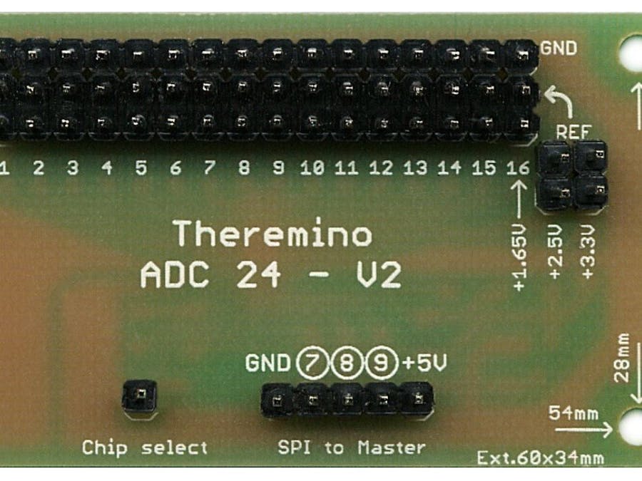
Connect the wire correctly. The proper order is GND, 7, 8, 9, +5, as shown in screen printing.
To start you start application HAL, you select the Pin 7 and you choose the type ADC24.
If you are unable to set the Adc24 on Pin 7 then the Master does not have the firmware updated (version 5.0 or following), or you have not downloaded l ’ HAL updated (version 6.6 or following).
At this point you should see the 16 ADC24 's PIN.
On Pin 7 adjust the characteristics common to all sixteen input Pin: The number of pins that are enabled, the number of samples per second and the type of filtering (The actual number of samples for each input decreases if you use several inputs and filters lenses).
Initially the pins of the ADC24 are all “Unused” and I'm yet to adjust. The regulations are very similar to normal system Pin Theremino. The only novelty is the overall speed (10, 12, 20, 30, 50, 60, 100, 120 … up to 19200 samples per second), the amplification for each channel (1, 2, 4 … up to 128), and the type of the channels (Single ended, Pseudo differential backups, or differential).
In all cases the minimum measurable voltage is zero Volts and the maximum is 3.3 Volts. To measure voltages outside this range should be used Add-ons.
Important to note that the inputs are always in pairs (1-2, 3-4, 5-6 ….. 15-16) and that the regulations apply to both inputs of the couple. The only independent regulation, You can enable or disable each individual Pin is “Biased to Vmax/2”.
The easiest to use is:
- Set the inputs as a differential (then work in pairs)
- Directly connect up to eight Geophones to pins 1-2, 3-4, 5-6, 7-8, 9-10, 11-12, 13-14, 15-16.
- Choose the preferred gain for each geophone (all in 1 for earthquakes, all in 64 for HVSR)
- Polarize the second Pin of each pair by enabling “Biased to Vmax/2”
- IMPORTANT: Check that only the second Pin of the couple is biased.
More detailed instructions in the user manual (you download at the beginning of this chapter) and in the instructions that you download with the application HAL.
ConstructionThe circuit board is very nice. Robust tracks, generous insulation and great attention to the arrangement of the components. The topology of connections to mass is optimized, with analog and digital areas well separated, to minimize the noise. The PCB is single-sided and all connectors are at step 2.54, also among the distant connectors.
This is the finished version of the ADC24, We recommend that you refresh the page with the F5 key, to make sure you see the updated images (the acronym V2).
The form Adc24 is very small, is off 60 mm as a Master, but high only 35 mm. The channels are 16 single ended, 15 pseudo differential backups, or 8 differential backups. The speed can be adjusted from 10 to 19200 samples per second. This means that you can get beyond the 1000 samples per second on all 16 channels simultaneously active. The gain of each channel can be adjusted from 1 to 128. The noise is very low and can almost compete with Theremino GeoPreamp.
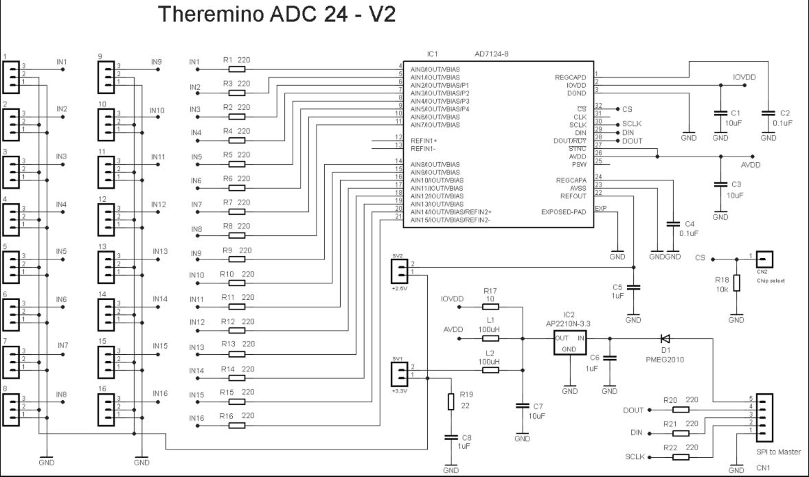
The AD7124-8 used is an ADC from Analog Devices, with superior characteristics to traditional LTC2499, used on Arduino shield. Has an internal amplifier, adjustable from 1 to 128 times, While at the Shield of Arduino you should add it externally. Has an extremely low noise (about 25 NV rms against 600 NV rms), and is also a breeze (up to 19200 samples per second against 15 about). So it's easier to use, twenty times less noisy, and more than a thousand times faster, of the Arduino ADC Shield. An AD7124-8 costs two or three dollars more than a LTC2499, but its excellent characteristics are worth them all.
The AD7124 also has superior characteristics compared to commercial loggers ADC. How you can? Because the AD7124 was designed in 2015, While the devices on the market, even the expensive ones, contain ADC who on average a decade.
Download the complete project containing the files Eagle printed circuit board, the schemas, the images i and the list of components:Adapter_ADC24_V2.zip


Comments