


Hand tools and fabrication machines | ||||||
 |
| |||||
Thank you so much for choosing the Vogurtime D2-5 Smart Car Kit. This kit will give you a preliminary understanding of the principles and techniques involved with automated control. With this kit, you will gain useful knowledge and skills which will lay a good foundation for further study. To get the most satisfaction from your D2-5 Smart Car project, we highly recommend that you read and follow all instructions and soldering recommendations carefully.
· How it WorksThis kit includes a 16mm wide track printed on the back of the included instruction sheet. The D2-5 Smart Car will drive along the track automatically. In fact, no matter which way the track curves, the D2-5 Smart Car will follow it. The D2-5 Smart Car works on the principle that light reflects more intensely off a lighter background than it does a dark background. In this case, we are using a red-light source and measuring the reflected red light with a photoresistor. By detecting and measuring the resistance across the photoresistors (one for each side), the D2-5 Smart Car can determine if it is on, or over, the black line. If one of the photoresistors senses that it has drifted off the line, resistance is increased, and voltage is reduced to the opposite side motor in order to correct its course back to the line. The red LEDs on the top, show which motor, or motors, are currently receiving power. For even more fun, use 1.5 – 2.0 cm electrical tape, or a pen or marker, and create your own tracks to challenge the D2-5 Smart Car!
· Specifications· Printed Circuit Board (PCB) Size: 104 mm x 72 mm x 1.6 mm
· Completed Project Size: 104 mm x 72 mm x 55 mm
· Working Voltage: 3V via 2 x AA Batteries
· Battery Case – Red wire is positive voltage, black (or other color) wire is ground
· IMPORTANT – Pay attention to the direction of the LEDs, capacitors, transistors, and the IC chip. Reversing any of these components may result in the D2-5 Smart Car not working properly.
· For LEDs – the short leg is the cathode/negative leg and it corresponds to the round hole on the PCB. The long leg is the anode/positive leg and it corresponds to the square hole on the PCB.· Tools Required
· Electric Soldering Iron (25-35 Watts recommended – higher temperatures or staying on the PCB for too long may damage the board and prevent D2-5 Smart Car from working
· Solder with Resin
· Tweezers
· Screwdriver
· Flat-head Screwdriver
· Needle-Nose Pliers
· Diagonal or Flush Cut Pliers
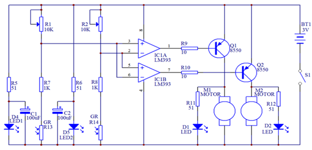
· Circuit Diagram· Component and Parts List
· Installation Steps
1. Install the Circuit
· We recommend that you start by installing the smaller, lower profile components first, and then add the larger, taller components as you go. Start with the resistors, then the 8-pin IC Holder (not the chip yet), the switch, potentiometers, transistors, capacitors and then the Red LEDs:
· The resistors have no polarity, so it does not matter which way they are installed, but the transistors, capacitors and LEDs DO have polarity, so pay attention to the pin direction. The round side of the transistor triode corresponds to the round side of the outline on the PCB.
· The short leg of the LED is the cathode/negative pin and corresponds to the flat side of the outline on the PCB and the round hole in the PCB. The long leg of the LED is the anode/positive pin and corresponds to the round side of the outline on the PCB and the square hole in the PCB.
· Pay close attention to the direction of the IC socket. The notched side of the IC socket corresponds to the notched side of the outline on the PCB.
· There is a vertical on one side of the switch and that corresponds to a small horizontal line located on the switch outline on the PCB.
· Pay close attention to the capacitor’s direction. The long pin is the anode/positive pin which goes in the hole marked “+” and insert the short pin into the negative hole marked “-“.
· Do not install the IC LM393 yet…
2. Install the Front “Wheel”
· Carefully place the PCB on its top side that has all of the components you just installed. Insert the support bolt of the caster into the hole and hand tighten the nut to secure it to the PCB – do not over-tighten. Install the caster and tighten snugly.
3. Install the Photoresistors and Clear LEDs
· It is important that the distance from the top of the caster wheel (screw cap top) and the photoresistors/LEDs is about 5mm or 3/16”. This spacing is very important. The top part of the caster is about 5 mm in height. (TIP: Use a little bit of masking tape to hold the LED/photoresistor in place while you are soldering – and remember you can always bend the leads to adjust them slightly if you need to lower the height)
4. Install the Battery Case
· The red wire goes to positive and the black (other color) wire goes to ground or negative. Peel the protective paper from the two-sided tape and stick it to the PCB. Solder the wires in place.
5. Test the Circuit
· Install 2 AA batteries and press the button switch.
· If the 2 clear LEDs light up, congratulations the installation is correct. If the LEDs don’t light, double check to make sure all the components are soldered well and installed in the correct direction. Make sure the batteries have power and are installed correctly.
· Power off the device, and let’s keep going…
6. Install the mechanical parts
· Stick the shaft through the center hole of the wheel, paying attention to the fact that the concave/hollow side of the wheel goes on the inside.
· Insert a three-way sleeve onto the steel shaft adjacent to the inside of the wheel. Then use a yellow gasket to hold the three-way shaft sleeve in place making sure the three-way sleeve can still spin freely.
· Place a gear onto the steel shaft followed by another three-way sleeve. This axle is now complete and ready to be secured to the PCB. Repeat on other side.
· Before you mount the axles to the PCB, put one yellow gasket on each screw under each three-way sleeve to increase the gap between the axle and the PCB in order for the gear to have enough rotation space. Use the 2.8mm screws to secure the axles to the PCB tightly. See picture below:
· Hold the wheel with one hand, keeping the shaft horizontal while you adjust the positions of the three-way sleeves and gears. The gear on the steel axle should line up with the gear slot. If not, adjust the position of the gear and gaskets so the gears line up with the slots and can spin freely.
· Finally, fit the two three-way sleeves one the steel axle over the screw projections of the fixed yellow washers and tighten with a small Philips-head screwdriver. Repeat for other side.
8. Install the Motors
· Insert a worm gear (screw thread) onto the shaft of the motor, and then insert the motor shaft through the designated hole on the PCB. Make sure the worm gear/screw thread comes into contact with the wheel gear. Please keep some distance and do not press the screw threads fully onto the gear of the motor.
Here is an example at below, the left screw thread just half onto the gear of the motor, which is contacting great with the wheel gear. The right one got 2/3 onto the gear of the motor, which is just ok. You can actually adjust the depth of the screw threads.
· Use the small black screws to fix the motors to the PCB – 2 screws per motor. Please pay attention to the wiring of the motor and connect the wires as shown below. Switching the wire connections will cause the motor and car to spin backwards. If you do wire one of the motors incorrectly, simply reverse the wires.
9. Final Test
· Insert the LM393 integrated chip into the IC holder. Make sure the notch in the end of the LM393 lines up with the notch on the end of the IC holder, which lines up with the notch painted onto the PCB.
· Power on the car and place it on the black oval test track. If the ambient lighting is too bright, the car may have difficulty detecting the line. Depending on the ambient light, you may need to calibrate the sensors by adjusting the potentiometers with a flathead screwdriver:
· Pick the car up, and while holding it so the wheels can turn and nothing is blocking the photoresistors, turn on the power and use a flathead screwdriver to adjust one of the potentiometers at a time.
· Slowly turn the potentiometers, one at a time, until you find the “sweet spot.”
· The “sweet spot” is attained when you can turn either potentiometer a little to the left, and the LED on the left will light up. Turn it a little to the right, and the right LED will light up. At this critical juncture, turning either potentiometer, in either direction will get the two LEDs to flash at the same time, and then one of them will light up and the other will go out immediately. They will alternate while following the lines.
· It sounds more challenging than it really is. We are confident you will be able to calibrate the car and get it to follow the lines. But, if for any reason, you are unable to get it to work, or have any questions at all, contact our support team at vogurtime-support@foxmail.com
10. Design your own tracks
· Use 1.5 to 2.0 cm black electrical tape to design your own tracks. Alternatively, a dark colored pen or marker would also work. Just make sure you are using non-toxic and water-soluble markers if you don’t want a permanent racetrack.
· Have fun and email us with any questions at vogurtime-support@foxmail.com
Other cool items at our store that you might be interested in!


Comments