Every electronics enthusiastic or student need a useful tool like an Oscilloscope in order to build and debug his projects.
A Digital Storage Oscilloscope is the most common configuration for this type of device. The Youtube is full with beginners build oscilloscopes that sweep signal from the right to the left or use some chart plotting. But a true DSO need to have the following features:
- A stable imagine or a signal capture which is refreshed
- A trigger in order to make a stable signal capture
- Buttons to change deflection on X and Y axis
- Some measurements tools.
Therefore with these specification I started to build a friendly interface with Processing 3 for what I will measure.
On the other side with measure principle I build the following flow chart:
It use DSO principle, a memory which store the recorded samples.
After I write the code for this flow diagram, I moved on graphic interface in Processing 3. And it look like:
Now the last element was to make transmission between PC and Arduino board and vice versa. The only option was USB.
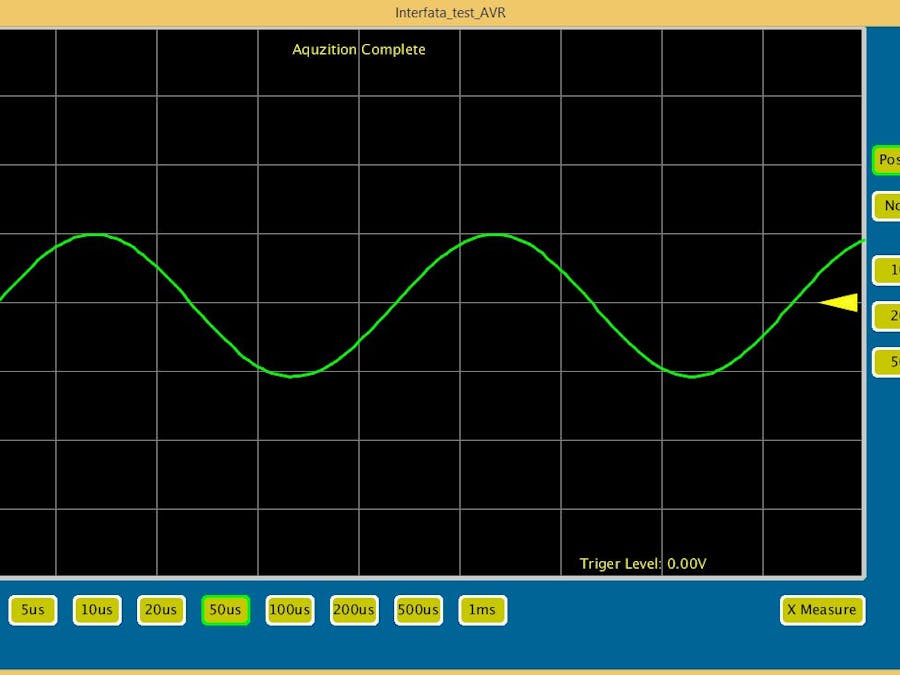
Finally I test with a sinusoidal wave and the results was:
And it looks like a real DSO only it has poor features:
- 5 kHz maximum input frequency
- 0-5 V input signal voltage
But, the good points are:
- Posedge and negedge trigger
- Some measurement tools
- Some display options
For more info you can read here.


_wzec989qrF.jpg?auto=compress%2Cformat&w=48&h=48&fit=fill&bg=ffffff)

Comments
Please log in or sign up to comment.