1. ESP8266 – Al-Cloud Inside (Black model: Flash size 8Mbit = 1MByte )
2. Breadboard
3. Arduino UNO;
4. Wires (jumpers);
5. Laptop;
6. Patient (a lot).
About This ProjectThis is a review of my previous post, but with a lot of improvements. ;-)
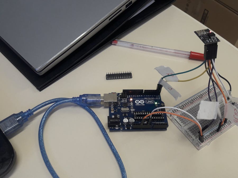
1. Before the Firmware Update1.1) You need to remove Arduino ATMega chip. The Arduino yellow LED should be on.
(Tip: Not use the 'trick' of linking Arduino RESET in GND ports because you can burn your ESP module. All the tests in this section keep the ESP temperature relatively low. If you can not touch the ESP due high temperature, turn off the connections immediately).
1.2) GPIO2 is not used to the firmware update.
1.3) Only VCC and CH_PD (CHip Down) must be connected at 3.3V Arduino ports.
1.4) Only GND and GPIO0 (general purpose input/ouput) must be connected at GND Arduino ports. GPIO0 in GND is to enable programming in ESP8266.
1.5) RST pin is used only to reset the ESP module. You must connect it in Arduino GND only to reset the current ESP firmare, and remove it for update the firmware. A quick 'blue blink' occurs when you connect and remove RST pin from Arduino GND.
1.6) TX with Arduino TX, and RX with Arduino RX.
2. Wiring for Firmware Update3.1) FLASH_DOWNLOAD_TOOLS_v2.4_150924 (latest version not works) (Available at: https://bbs.espressif.com/viewtopic.php?f=57&t=433&hilit=FLASH_DOWNLOAD_TOOLS_v2.4_150924)
3.2) AT_V1.1_on_ESP8266_NONOS_SDK_V1.5.4 (latest version not works) (Available at: https://www.electrodragon.com/w/File:AT_V1.1_on_ESP8266_NONOS_SDK_V1.5.4.zip)
3.3) Manufacturer firmware: ai-thinker-v1.1.1.bin. (Available at: http://wiki.aprbrother.com/wiki/Firmware_For_ESP8266)
4. Update the Firmware4.1) Open the Flash Download Tools executable.
4.2) Set the fields as follows:
ESP8266_NONOS_SDK_V1.5.4\AT_bin\blank.bin >>> 0xFE000
ESP8266_NONOS_SDK_V1.5.4\AT_bin\esp_init_data_default.bin >>> 0xFC000
ESP8266_NONOS_SDK_V1.5.4\AT_bin\512+512\user1.1024.new.2.bin >>> 0x1000
ai-thinker-v1.1.1.bin >>> 0x0
4.3) Configure the SPI Flash settings as follows (Note: according these wikis...
https://github.com/arendst/Tasmota/issues/683
https://github.com/arendst/Tasmota/wiki/Theo's-Tasmota-Tips
https://github.com/letscontrolit/ESPEasy/issues/474
...all ESP8266 supports "DOUT" SPI MODE).
4.4) Click on START and wait until the upload be done.
4.5) Close the Flash Download Tools.
5. After Deploying the Firmware5.1) Disconnect: RX, TX, and GPIO0 connections.
5.2) Unplug Arduino from USB port.
5.3) Reconnect the Arduino in USB port. At this step, these pins should be used:
VCC and CH_PD <---> Arduino 3.3v
GND <---> Arduino GND
RX <---> Arduino RX
TX <---> Arduino TX
5.4) Open Arduino IDE.
5.5) Choose Tools -- Board -- Generic ESP8266 Module.
5.6) Select the proper ESP settings as follows:
5.7) Open the Serial Monitor.
5.8) At this step, if you remove and connect again the CH_PD wire, you should see some characters in the serial monitor. CH_PD wire must be connected to send/receive AT messages. If you do not see any characters, something is wrong and you have to deploy the firmware again.
5.9) Test the AT commands as follows:
- The baudrate for this ESP8266 model is 115200 bps.
- Remember to unplug RX, TX and GPIO0 after the firmare update. If you don't do it, you will need to redo the firmaware update again when you power off your ESP8266.


_ztBMuBhMHo.jpg?auto=compress%2Cformat&w=48&h=48&fit=fill&bg=ffffff)


Comments
Please log in or sign up to comment.