


Hardware components | ||||||
 |
| × | 1 | |||
_ztBMuBhMHo.jpg?auto=compress%2Cformat&w=48&h=48&fit=fill&bg=ffffff) |
| × | 1 | |||
 |
| × | 1 | |||
Components and Supplies
ESP8266 – Al Cloud Inside
Arduino UNO
About this project
Hi. This project is based on this other project: https://create.arduino.cc/projecthub/jaiprak/control-led-from-web-app-using-esp8266-serial-wifi-module-cdf419?ref=search&ref_id=esp8266%20car&offset=2
I started this project with the intent to control a robot car with wireless, but no success still with this module. I’m not glad with ESP8266 module. I'm really think about to try other alternatives like Wemos, Beagle, or similar with embedded wireless. Also, I want to write this project to do more than display simple Web page queries with ESP8266. When I acquire this module I found many problems:
1) Performance to deploy, receive/send requests
2) Difficult to use with Arduino, it is plug-an-pray (really)
3) Difficult to setup SSID, IP and MAC
4) Memory faults are common in successive sketch deploys
5) I need reinstall software with Arduino IDE each time that I power on it again (solved in final remarks).
6) I’m was not able to use analogic or other digital ports than RX/TX (0,1)
7) You need to remove ATmega chip to use this module (strange solution because pins of ATmega chip are very thin and they are easy to broke).
8) I always get working after bug deploys, simply removing USB cable and re-plug, instead try continuous deploys. Always verify if your serial port is given again after you re-plug Arduino USB cable.
Required Components: 1. Breadboard; 2. LED; 3. Arduino UNO; 4. Wires; 5. Laptop; 6. Patient (a lot).
Setting Up Arduino IDE
- Install the ESP8266 Board Package:
Arduino -> Preferences -> Additional Board Manager’s URL -> http://arduino.esp8266.com/package_esp8266com_index.json.
- After add it, click OK.
Now, restart Arduino IDE. Then continue: Tools -> Board -> Boards Manager… Search by esp8266 by ESP8266 Community. Click and install it. Restart Arduino IDE again.
Then, continue: Tools -> Board -> Generic ESP8266 Module. My settings are as follow:
Board: “Generic ESP8266 Module”
Flash Mode: “DIO”
Flash Frequency: “40MHz”
CPU Frequency: “80MHz”
Flash Size: “4M (1M SPIFFS)
Debug port: “Serial”
Debug level: “None”
Reset Method: “ck”
Upload speed: “115200”
Port: my USB port
Programmer: AVRISP mkII
Wiring
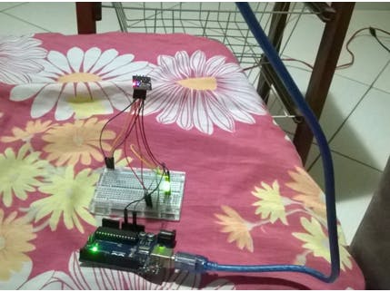
I used a solderless breadboard due multiple power and ground connections.
I tryed to use a Arduino breadboard shield to avoid solderless breadboard, but this module only does software deploy directly with Arduino board.
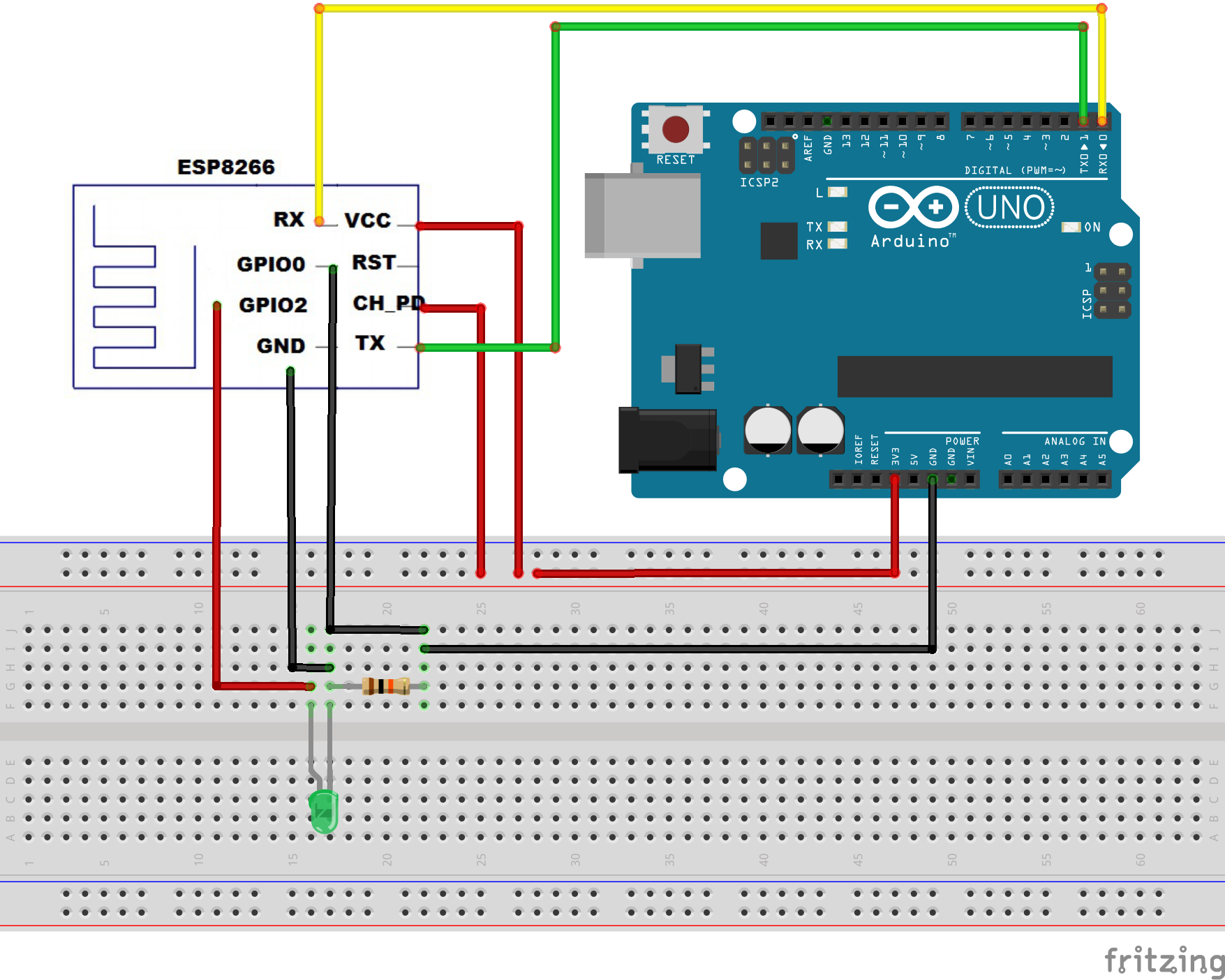
ESP8266 -- Arduino
VCC 3.3V
CH_PD 3.3V
GPIO2 3.3V
GND GND
GPIO0 GND
TX TX
RX RX
I not observed problems to keep GPIO0 pluged even after sketch deploy, but most authors recommend remove it after sketch deploy.
Power up ESP8266: ESP8266 module works on 3.3V, then connect VCC, CH_PD and GPIO2 to 3.3V. I used a 10K resistor only to avoid high amperage to my led.
TX/RX pins are used to program this module, for serial I/O, and debugging (but I’m not confidence about other alternatives instead serial monitor). When I flash the ESP8266 it is need to use GPIO0 in GND to put this module in programming model. My suggestion is put wiring according its connections, i.e., power wiring, ground wiring, and tx/rx wiring.
After upload with flash technique, i.e., transfer code to module you can remove GPIO0 (it is used to bootloader and programming tasks). Also, you can reset module by disconnecting the CH_PD (Chip Power Down), or use reset button, or unplug USB cable. I prefer this latter to avoid remove thin cables from module, and unplug USB is simpler when I need to upload code again.
Arduino sketch:
This code was used to turn on and off the led managed by GPIO2 control (then I use pin number 2). I tried many things to access other Arduino board pins but no success. I’m welcome to suggestions about how use ESP8266 to send/receive data of other pins.
How to connect your smatphone
Connect at your wireless module SSID, something like AI-THINKER-DCFFBB. Then, use your browser to navigate to URL: http://192.168.4.1.
Remember to put your wireless device in this same IP domain. I was not able to figure out how to change ESP8266 IP address, and password. Suggestions are welcome.
Important: note that HTML contents in ESP8266 must be tiny to avoid large delays. Avoid tables, figures, and unnecessary code. I noted also that automatic refresh is not a good alternative to refresh contents, maybe due internal clock from ESP8266.
---
/* Create a WiFi access point and provide a web server on it.
Author: Lucio A. Rocha
Last Update: 21 Aug 2016
*/
#include <ESP8266WiFi.h>
#include <WiFiClient.h>
#include <ESP8266WebServer.h>
/* Set these to your desired credentials. */
const char *ssid = "Microcloud_2";
const char *password = "654321";
ESP8266WebServer server(80);
const int led = 2; //GPIO2
/* Just a little test message. Go to http://192.168.4.1 in a web browser
* connected to this access point to see it.
*/
void handleRoot() {
int size=1000;
char temp[size];
int sec = millis() / 1000;
int min = sec / 60;
int hr = min / 60;
snprintf ( temp, size,
"<html>\
<head>\
<title>MicroCloud</title>\
<style>\
body { background-color: #cccccc; font-family: Arial, Helvetica, Sans-Serif; Color: #000088; }\
</style>\
</head>\
<body>\
<h3>You are connected on MicroCloud #2!</h3>\
<p>Uptime: %02d:%02d:%02d</p>\
<p>Status: Light ON</h1></p>\
<p><a href=\"http://192.168.4.1/on\"><h1>Turn ON</h1></a></p>\
<p></p>\
<p><a href=\"http://192.168.4.1/off\"><h1>Turn OFF</h1></a></p>\
</body>\
</html>",
hr, min % 60, sec % 60
);
server.send ( 200, "text/html", temp );
}
void setup() {
delay(1000);
Serial.begin(9600);
Serial.println();
Serial.print("Configuring access point...");
/* You can remove the password parameter if you want the AP to be open. */
WiFi.softAP(ssid, password);
IPAddress myIP = WiFi.softAPIP();
Serial.print("AP IP address: ");
Serial.println(myIP);
pinMode(led, OUTPUT);
digitalWrite ( led, HIGH );
//URLs available to query
server.on("/", handleRoot);
server.on ( "/on", turnON );
server.on ( "/off", turnOFF );
server.begin();
Serial.println("HTTP server started");
}
void turnON(){
digitalWrite ( led, HIGH );
int size=1000;
char temp[size];
int sec = millis() / 1000;
int min = sec / 60;
int hr = min / 60;
snprintf ( temp, size,
"<html>\
<head>\
<title>MicroCloud</title>\
<style>\
body { background-color: #cccccc; font-family: Arial, Helvetica, Sans-Serif; Color: #000088; }\
</style>\
</head>\
<body>\
<h3>Request: Light ON</h3>\
<p>Uptime: %02d:%02d:%02d</p>\
<p></p>\
<p>Status: Light ON</h1></p>\
<p><a href=\"http://192.168.4.1/on\"><h1>Turn ON</h1></a></p>\
<p></p>\
<p><a href=\"http://192.168.4.1/off\"><h1>Turn OFF</h1></a></p>\
</body>\
</html>",
 hr, min % 60, sec % 60
);
server.send ( 200, "text/html", temp);
}
void turnOFF(){
digitalWrite ( led, LOW );
int size=1000;
char temp[size];
int sec = millis() / 1000;
int min = sec / 60;
int hr = min / 60;
snprintf ( temp, size,
"<html>\
<head>\
<title>MicroCloud</title>\
<style>\
body { background-color: #cccccc; font-family: Arial, Helvetica, Sans-Serif; Color: #000088; }\
</style>\
</head>\
<body>\
<h3>Request: Light OFF</h3>\
<p>Uptime: %02d:%02d:%02d</p>\
<p>Status: Light OFF</p>\
<p><a href=\"http://192.168.4.1/on\"><h1>Turn ON</h1></a></p>\
<p></p>\
<p><a href=\"http://192.168.4.1/off\"><h1>Turn OFF</h1></a></p>\
</body>\
</html>",
hr, min % 60, sec % 60
);
server.send ( 200, "text/html", temp);
}
void loop() {
server.handleClient();
}
Final remarks
I tested this module with 9600 and 115200 baud rates without problems. The red light must be on ever time, even when you plug your module by first time. This simple observation saves a lot of time to beginners. After flash code, the blue light should blink periodically to show module activity. If your code and wireless are Ok you still need to unplug TX/RX wiring before exit. (GND+All 3.3V wiring). If you don’t do this you will need to re-flash again your code when you power on your module again. Thanks. Please, give me suggestions about this text. I’m still trying to move a robot car with ESP8266.

Comments
Please log in or sign up to comment.