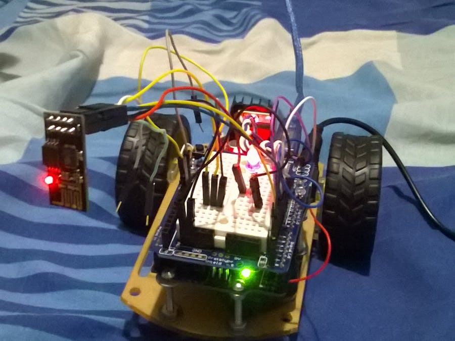
This document is about my attempt to control an Arduino robot with L298N motor drive and AI-Thinker ESP8266. This robot was named UTFPRBot version 1.0.
Here is a YouTube video to demonstrate it running:
This project explains how to create this Arduino robot. Also, I describe my personal steps to simplify the deployment of programs to control this robot.
Components and Supplies- ESP8266 – Al Cloud Inside
- Arduino UNO
- Motor Drive L298N
- Solderless breadboard shield
- Jumpers (a lot)
- LED
- 1K Resistor
- 2 DC motors of 5V
- Robotic base with 2 tiers and 1 omnidirectional tier.
- Smartphone
This project is the result of a lot of effort to construct a simple robot controlled by ESP8266. I have not found good sources on the Internet that describe a simple way to build robots with ESP8266. Also, I found a lot of information that empirically is not necessary to make it, even with comments in forums. This project proposes to simplify this difficult process.
SettingsThis is our goal:
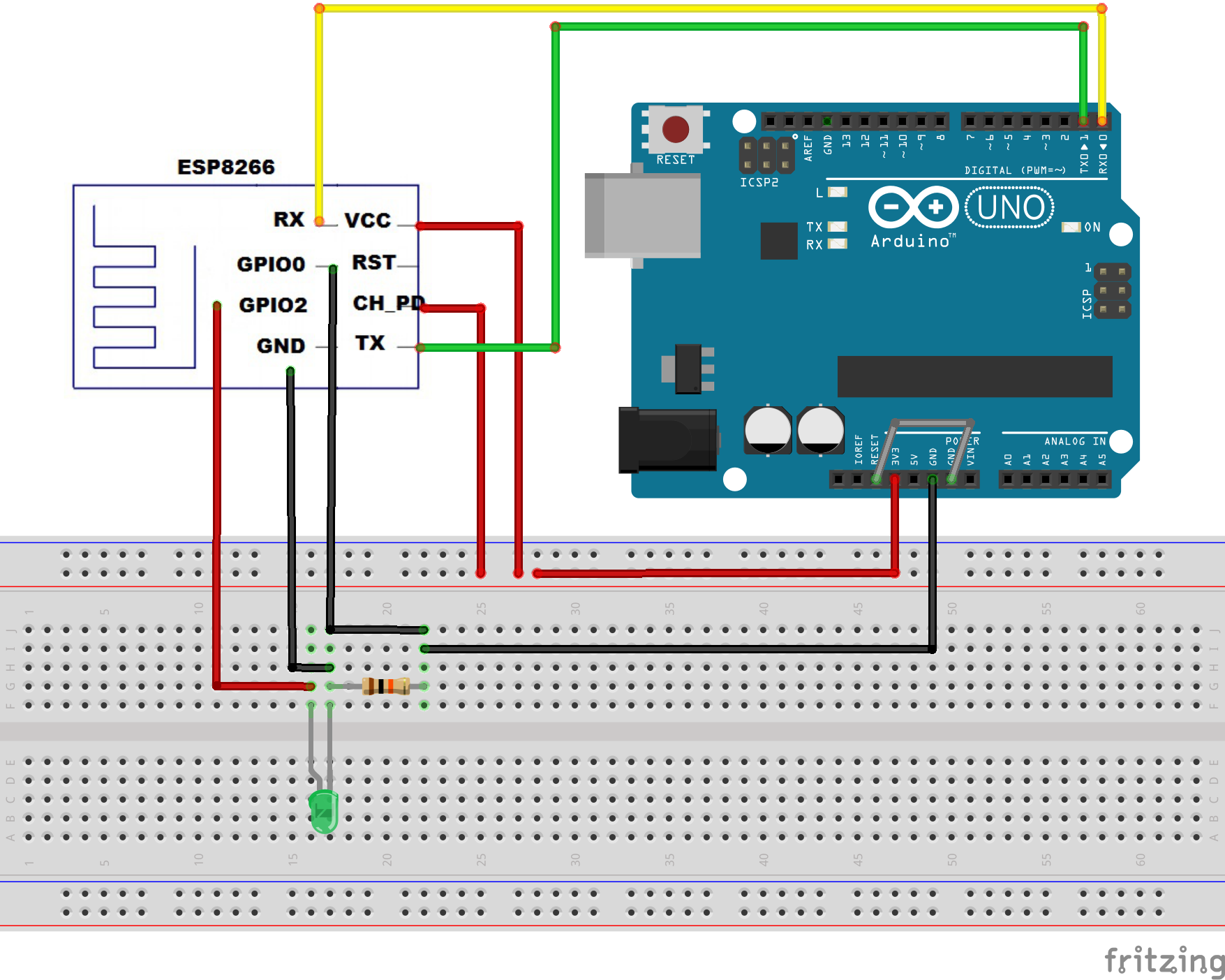
I put an LED in the circuit just to know that the ESP8266 is really powered with 3.3V, but you can use a multimeter to verify voltage. I used a solderless breadboard due to multiple connections. I tried to use an Arduino breadboard shield to avoid using a solderless breadboard, but this module only does software deployed directly with the Arduino board.
ESP8266 -- Arduino
- VCC 🠚 3.3V
- CH_PD 🠚 3.3V
- GPIO2 🠚 3.3V
- GND 🠚 GND
- GPIO0 🠚 GND
- TX 🠚 TX
- RX 🠚 RX
This step is done once only to assure that firmware is updated.
a) ESP8266 deployment only works without ATMega chip. But you can plug in Arduino a single wire in RST and GND. Then, only the board will be used, and not the ATMega chip.
b) You need to plug GPIO0 to deploy, and you need to remove GPIO0 after the sketch deploys.
c) You need to always use RST pin before deploying to sync your ESP. Do RST with GND quickly, and observe the light blink. If nothing happens, try again until you see a blue blink. After the blue blink, remove RST wire.
d) Power up ESP8266. Connect VCC, CH_PD and GPIO2 to 3.3V. I used a 1K resistor only to avoid high amperage to my LED.
e) You need to plug Rx🠚Rx and Tx🠚Tx to deploy firmware in ESP8266.
f) After deployment, remove wires in this order: TX and RX, GPIO0, VCC. Plug in again only VCC to verify that your ESP8266 keeps your deploy.
Software:- Manufacturer firmware: ai-thinker-v1.1.1.bin. (Available at: http://wiki.aprbrother.com/wiki/Firmware_For_ESP8266)
- FLASH_DOWNLOAD_TOOLS_v2.4_150924
1) Make the wiring of your ESP8266 module as illustrate in figure.
2) Open the FLASH_DOWNLOAD_TOOLS_v2.4_150924/ESP_DOWNLOAD_TOOL_V2.4.exe.
3) Open “Device Manager” in Windows to verify COM port connectivity when you plug in the USB Arduino cable. Test your serial COM port in the FlashDownloadTools program. Just click the START button, but first uncheck the download path config checkboxes. DETECT INFO and MAC Address areas should display ESP8266 information.
3) Now, check the path boxes and fill the fields as illustrated in figure:
esp_iot_sdk_v1.5.0_15_11_27\esp_iot_sdk_v1.5.0\bin\esp_init_data_default.bin à0xfc000
esp_iot_sdk_v1.5.0\bin\blank.bin à 0xfe000
esp_iot_sdk_v1.5.0\bin\boot_v1.4(b1).bin à 0x00000
esp_iot_sdk_v1.5.0\bin\at\512+512\user1.1024.new.2.bin à 0x01000
ai-thinker-0.9.5.2.bin à 0x00000
4) Click START and wait - SYNC until a complete flash of firmware files.
5) After deployment, remove wires in this order: TX and RX, GPIO0, VCC. Plug in again only VCC to verify that your ESP8266 keeps your deployed code.
At this step, you need to put ITEADLIB_Arduino_WeeESP8266-master in C:\Program Files (x86)\Arduino\libraries. Also, you need to uncomment the following line in ESP8266.h:
#define ESP8266_USE_SOFTWARE_SERIAL
At this step, you need to enable ESP8266 modules in Arduino IDE. (File 🠚 Preferences: Informe URL: http://arduino.esp8266.com/package_esp8266com_index.json). After, upload the ESP8266 modules (I installed all that I found useful and mentioned ESP8266).
In Arduino IDE, choose Generic ESP8266 Module. The value was set as follows:
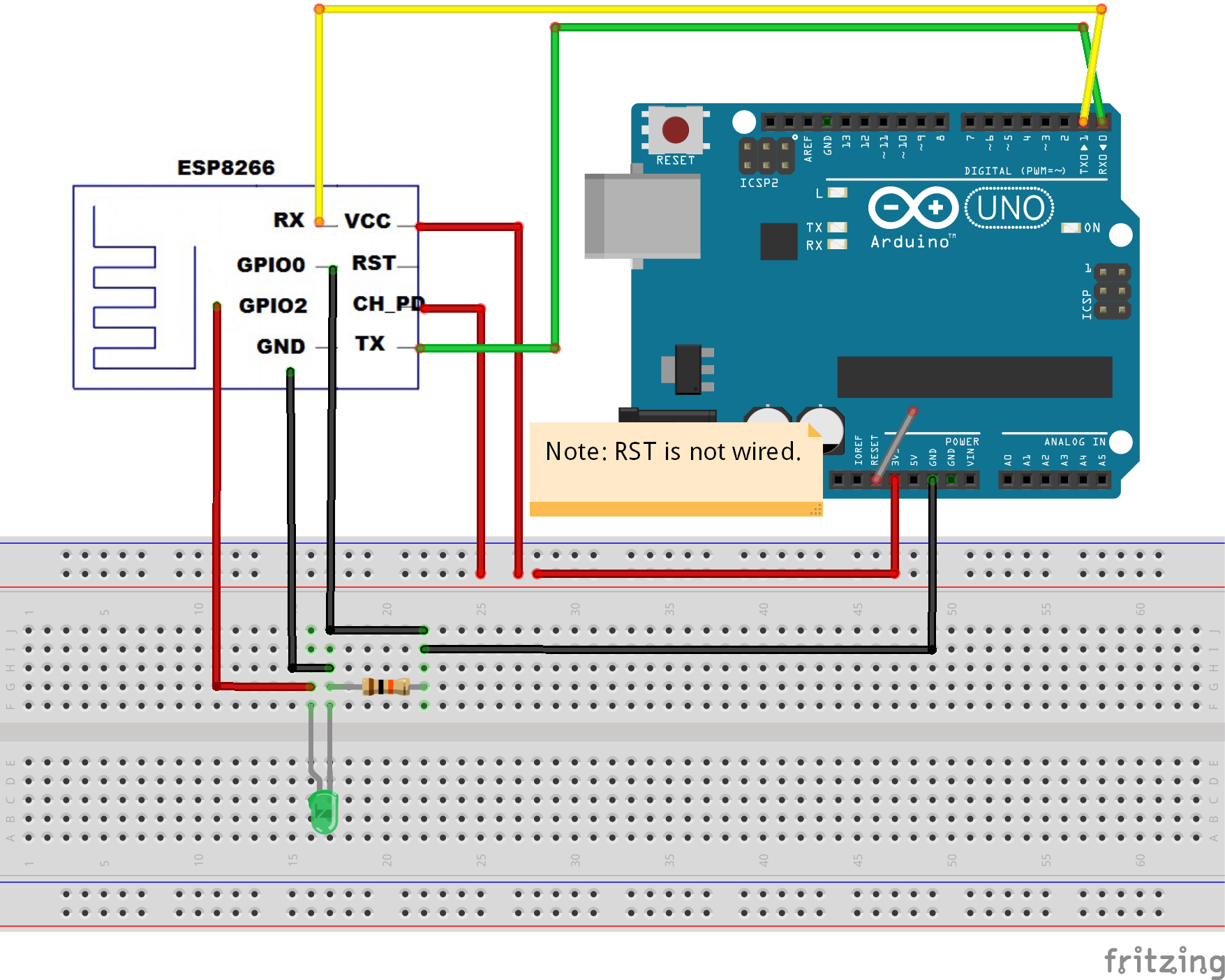
Then upload the new sketch: Web Server to Receive HTTP Connections to move the robot. Remember the wiring to deploy sketches in ESP8266:
- VCC 🠚 3.3V
- RST 🠚 GND
- GPIO0 🠚 GND
- GND 🠚 GND
- TX 🠚 TX and RX 🠚 RX
Remember the wiring to remove after deploy:
- TX and RX
- GPIO0
- RST
- VCC.
Now, plug again only VCC to assure that your sketch was deployed. Use the Code1 (attached) to: Create a WiFi access point and provide a web server on it to move robot.
Step 3) Deploy Arduino Sketch to read ESP8266 data from SoftwareSerialNow, you need to deploy code to Arduino ATMega chip. Note that I am using a solderless breadboard shield. To avoid removing/placing the ATMega chip many times, now you need only remove RST wire from GND.
Important: To read data from SoftwareSerial, you invert the connection of RX/TX wiring that ESP8266 uses to connect to Arduino.
Wiring
Use the Code 2 (attached) to:
- Parse serial data from ESP8266 and
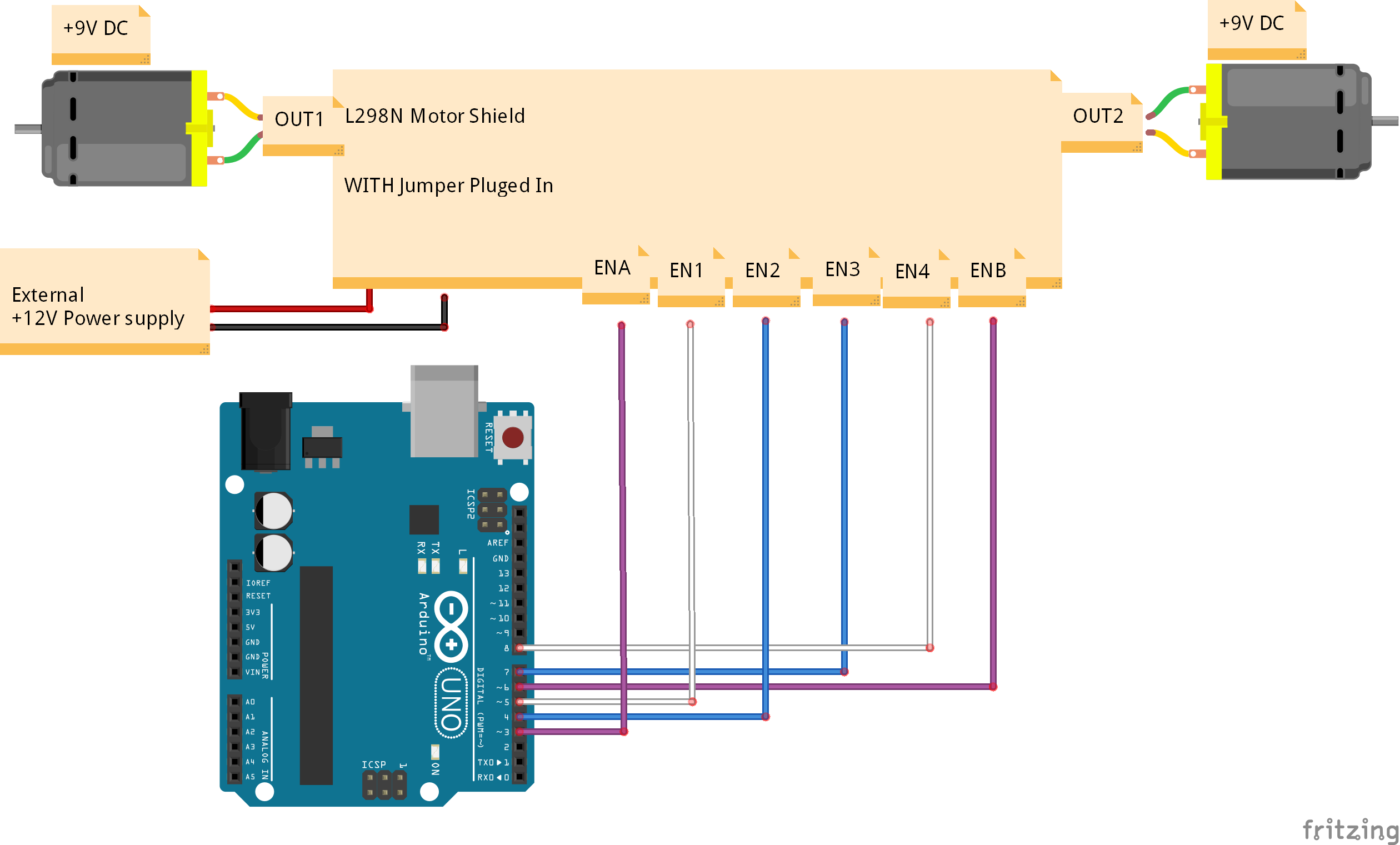
- Move motors controlled by L298N motor drive.
Wiring
- Connect your smartphone in the ESP8266 wireless AP (it is not necessary to change the IP address of you smartphone or any host connected to ESP8266).
- Go to URL: http://192.168.4.1
- Simply select options and have fun!
Final remarks:
LLC (Logic Level Converter): I observed that many forums recommend using an LLC to connect ESP8266 to Arduino. I bought one and, to my surprise, I was not able to use it with ESP8266 and Arduino (it does not work to deploy or send/receive serial data). Apparently, its use is not necessary to update firmware, nor to deploy new programs within ESP8266. Some assumptions:
- ESP8266 supports until +6V (I looked that an Arduino forum mentioned that ESP8266 has internal capacitors to support until +6V (and this information is in manual of ESP8226). I only use ESP8266 with Arduino ports, so I believe that 50mA from the Arduino will not burn ESP8266, because it can support nearly 250mA.
- Arduino ports are nearly 50mA.
- ESP8266 ports supports nearly 250mA.
- I will only connect ESP8266 with Arduino.
- Power supply: I was not able to use rechargeable 9V batteries to supply Arduino + ESP8266 + L298N due to quick consumption. However, for my purposes, I am comfortable using a USB with larger wiring to supply L298N motor drive.
- I still do not known how to change the MAC address (probably recompiling files) nor how to change the IP address from ESP8266 (probably with AT commands; maybe dealing with AT commands (Step 1) and changing the IP).
Doubts, suggestions and comments are welcome.


_ztBMuBhMHo.jpg?auto=compress%2Cformat&w=48&h=48&fit=fill&bg=ffffff)


_3u05Tpwasz.png?auto=compress%2Cformat&w=40&h=40&fit=fillmax&bg=fff&dpr=2)
Comments
Please log in or sign up to comment.